- 15
- Nov
Analysis of Parallel Resonant Inverter for Intermediate Frequency Power Supply
Analysis of Parallel Resonant Inverter for Intermediate Frequency Power Supply
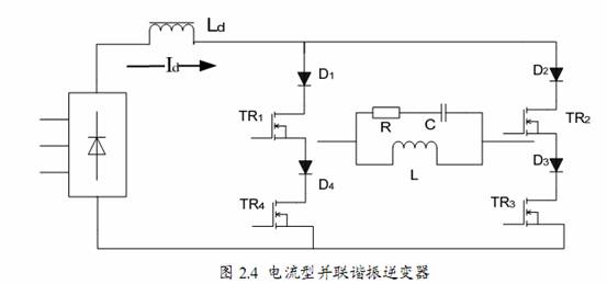
Parallel resonant inverter, its load is parallel resonant load. Usually a current source is required to supply power. In induction heating, the current source is usually composed of a rectifier and a large inductor. Due to the large inductance value, it can be approximated that the current at the input end of the inverter is fixed. Alternately turning on and turning off the controllable devices on the inverter can obtain an alternating square wave current at the output of the inverter. The amplitude of the current depends on the current value of the input of the inverter, and the frequency depends on the device. operating frequency. As shown in Figure 2.4, the inverter that connects the compensation capacitor and the load coil (L and R) in parallel as the load of the inverter bridge is called a parallel resonant inverter. A large inductance Ld is connected in series with the DC power supply in the parallel inverter, so the load current is constant and is not affected by the change of load impedance. When the load power factor is not 1, the reactive voltage component of the load will be added to the switching device. In order to prevent the IGBT from being damaged by the reverse voltage, a fast diode must be connected in series with the IGBT. Even if an IGBT module is used, because there is an anti-parallel fast diode inside, the IGBT will not withstand the reverse voltage, and the series fast diode cannot be cancelled, otherwise the device will be damaged by the circulating current caused by its reverse voltage. According to the voltage and current phase relationship of the load tank circuit, the parallel inverter may work in three working states: resonance, inductive and capacitive states. Due to the existence of large inductance Ld, in order to keep the current continuous, during the commutation process, the upper and lower bridges The arm IGBT must follow the principle of first turning on and then turning off, that is, there should be an overlap time RT. The length of the commutation overlap time is closely related to the inverter output wiring inductance. The larger the inductance, the longer the time.。