
- 22
- Feb
Principles of PLC Operating Condition Monitoring System for Induction Melting Furnace
Principles of PLC Operating Condition Monitoring System for Induction Melting Furnace
The PLC operating status monitoring system of the induction melting furnace is combined with a 10-inch display screen, with functions such as controllable and adjustable, automatic display, and automatic memory.
1. The PLC external control console of the induction melting furnace is equipped with DC voltmeter, DC ammeter, intermediate frequency voltmeter, intermediate frequency meter, intermediate frequency power meter, temperature display instrument, etc. All equipment parameters can be displayed intuitively. The Siemens 10-inch touch screen can easily set the oven or melting process, and can display the melting temperature and equipment power and other parameter curves in real time. The console is designed with control power switch, intermediate frequency manual and automatic switch, emergency stop button, power indicator light, intermediate frequency indicator light and fault indicator warning light.
2. The intermediate frequency power supply control board is designed with a temperature closed-loop control interface. The temperature control instrument is selected from Japan Island Electric SR3 with a PID adjustment instrument. The far-infrared optical fiber thermometer is selected from Germany’s Optris CT series copper special thermometer, measuring temperature -40 -900°C. First, set the heating temperature and annealing speed on the temperature control instrument or PLC touch screen. After the power is turned on, the thermometer measures the heating temperature in real time and feeds it back to the temperature control instrument. The temperature control instrument compares the measured temperature with the set heating temperature and outputs the simulation The signal is sent to the intermediate frequency main control board, and the main control board automatically adjusts the trigger angle of the thyristor according to the level of the signal, so that the output power of the power supply is adjusted with the level of the analog signal, achieving the purpose of temperature closed-loop control. When the feeding speed of the copper tube is adjusted, the thermometer detects the temperature change of the copper tube, and outputs the corresponding current signal according to the comparison between the detected temperature and the set temperature
For the intermediate frequency control board, the output power of the intermediate frequency power supply will be adjusted to the required power accordingly to achieve the purpose of temperature closed-loop control.
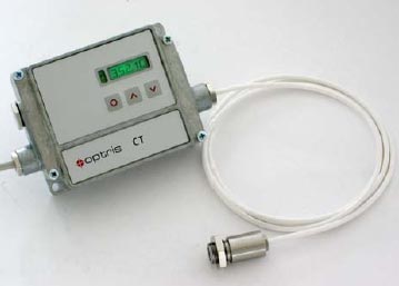
CT series Optris special thermometer for copper measurement
3. The intermediate frequency switch of the external control console is designed with manual and automatic operation knobs. When the automatic mode is selected, the equipment adopts a temperature closed-loop control system, and the equipment power automatically adjusts the output power according to the set melting temperature. The intermediate frequency power supply control board is designed with a temperature closed-loop control interface. The temperature control instrument selects Shimadden SR3 with PID adjustment instrument, and the far-infrared fiber optic thermometer selects the German Optris CT series special thermometer, and the temperature is 385-1600℃. First set the melting temperature on the temperature control instrument or PLC touch screen. After the intermediate frequency power supply is started, the thermometer measures the crucible temperature in real time and feeds it back to the temperature control instrument. The temperature control instrument compares the measured temperature with the set heating temperature and then outputs an analog signal to IF main control board, the main control board automatically adjusts the trigger angle of the thyristor according to the level of the signal, so that the output power of the power supply can be adjusted with the level of the analog signal. When the user selects the manual operation mode, the device melts at the maximum output power.
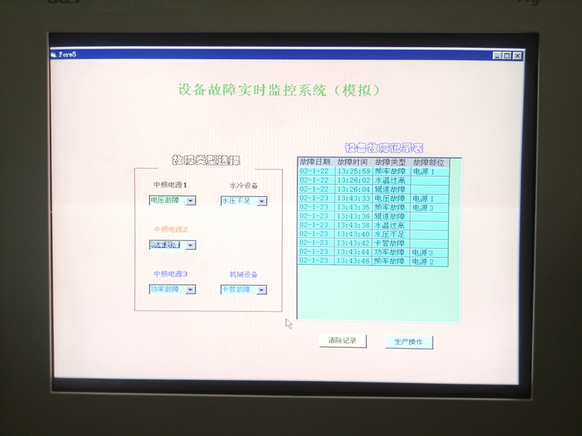
4. In addition to displaying the operating status of the equipment, the touch screen can also monitor equipment failures and provide maintenance tips and other information. The operating guide is accompanied by equipment operating procedures, common failure phenomena and treatment methods.
IF power supply PLC equipment operating status monitoring system can have the following functions:
1) Complete melting control management functions, automatic fault diagnosis, automatic lining sintering and other functions. 2) 2) Perfect melting process control function and perfect monitoring, alarm and fault self-diagnosis function. 3) 3) Complete sound and light alarm system, which will alarm the following conditions:
The frequency conversion cabinet is opened;
The capacitor is damaged;
The temperature of the cooling water in each circuit of the power supply is too high;
Power cooling water pressure is too low;
The temperature of the furnace cooling water is too high;
The pressure of the furnace cooling water is too low;
The furnace selection/isolation switch is wrong;
The rectifier part of the variable frequency power supply has no DC output;
Grounding / leaking furnace detection alarm.
Control cabinet and power distribution installation and wiring technology:
Main switch: Incoming six-wire eight-wire system, that is, six-phase power supply, one-phase ground wire, and one-phase neutral wire are fixed with wiring lugs. The switch specification capacity is less than the load of the sub-switch and equipment. The main switch is far away from the DC24V power supply. The main circuit uses AC380V or AC220V, and the control circuit uses DC24V.
The ground line bar and the zero line bar are marked and fixed respectively, and a cross-grounding wire is designed on the control cabinet door.
The control direction of each sub-switch is marked on the control cabinet door.
The control cabinet is designed with a ventilation device (axial flow fan and air inlet grille form convection), and the air exchange port is equipped with a dust filter.
The lighting device in the control cabinet is intact to ensure that the door is turned on, or a switch is installed to control the lighting.
All line routing specifications are incorporated into the trunking, and the line number is clearly marked. The wire number does not fade and conforms to the drawing. The wire diameter is selected appropriately, and the infrared thermometer checks that there is no overheating or overloading of the lines.
Install insulation protection boards and rat-proof boards for exposed switch wiring and copper bars.
In front of the control cabinet, lay rubber pads that meet the safety requirements, such as insulation grade and size.
For motor control mode: air switch + contactor + thermal relay or motor protection switch + contactor for control system.
Fixing method: The electrical components are fixed on the control cabinet with 35mm standard guide rails.
Wiring method: Fix with terminal and mark the wire number;
PLC part: The PLC power supply has corresponding protection facilities; the PLC is installed firmly and well ventilated; the input and output are distinguished by two lines; there are more than 5 I/O points for backup.
Inverter part: the capacity is one level higher than the rated power of the motor; the incoming line has a reasonable protection system;
Use multi-core flexible wire wiring trough in the cabinet; 220V and DC24V wire colors are separated; the wires have vacant space in the trough; the outlet of the power distribution line is protected with rubber; the end of the wire has a standard wire number.
Wiring terminal part: the terminal is installed at the lower end of the control cabinet, 380V and DC24V are installed separately; the power distribution cabinet is connected to the peripheral equipment with aviation plugs or wiring terminals.
The external trunking is standard, safe, resistant to stepping pressure, and does not deform.
The production line is in the cable and wire trough in the trench, and is reasonably distributed with the water and air paths.
The connection line number marks of the input and output parts of the equipment are clear, durable, and easy to find on site; they will not be lost due to replacement of parts;