
- 01
- Aug
Quick change chuck for quenching inductor
- 02
- Aug
- 01
- Aug
Quick change chuck for quenching inductor
The connection between the inductor and the quenching transformer requires strong electrical connection, low resistance, and reliability. The early design of the inductor and the transformer contact plate are connected with bolts and nut washers: the intermediate frequency sensor has two rows of M12 bolts, a total of 10 bolts; the high frequency sensor also has M8 or M10 bolts, a total of 4 bolts. It is time-consuming and laborious to load and unload the sensor once, and the cooling water inlet and outlet pipes need to be connected to the sensor, which increases the auxiliary time.
Quick-change chuck for sensor
The picture shows a quick-change chuck for a sensor, which is composed of a contact plate body, a pressing handle, a pressing block, a sealing ring and a water inlet valve. In the middle of the front is the insertion port of the sensor, and the two sealing rings are the water inlet and outlet of the sensor. When the sensor with the standard structure of the connection block enters the insertion port, twist the handle 3, the bakelite press block presses the connection block to the bottom surface of the insertion port, and the water and electricity connection is completed at one time. When replacing the sensor, the water inlet valve 5 can be closed. With this structure, it takes about 10 seconds to replace a sensor, which greatly improves work efficiency and saves labor. This chuck has been widely used in production and is more suitable for high frequency power below 60kW.
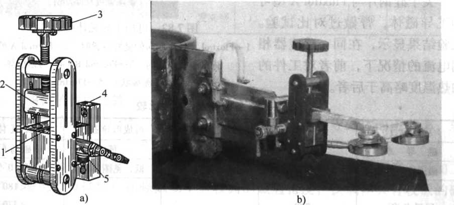
Figure Sensor quick change chuck and sensor
a) Quick-change chuck b) Quick-change chuck with sensor
1 a sealing ring 2-pressure block 3-handle 4 a contact plate body 5-water inlet valve