
- 07
- Nov
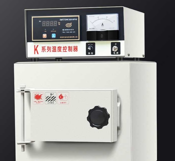
Muffle furnace temperature controller instructions
Muffle furnace temperature controller instructions
1. Operation and usage
1 . When the controller is powered on, the upper row of the display window displays ” index number and version number ” , and the lower row displays ” range value ” for about 3 seconds, and then it enters the normal display state.
2 . Reference and setting of temperature and constant temperature time
1 ) If there is no constant temperature timing function:
Click the ” set ” button to enter the temperature setting state, the lower row of the display window displays the prompt “SP” , the upper row displays the temperature setting value (first place value flashes), and you can press the shift, increase, and decrease keys Modify to the required setting value; click the ” Set ” button again to exit this setting state, and the modified setting value will be automatically saved. In this setting state, if no key is pressed within 1 minute, the controller will automatically return to the normal display state.
2 ) If there is constant temperature timing function
Click the ” set ” button to enter the temperature setting state, the lower row of the display window displays the prompt “SP” , the upper row displays the temperature setting value (first place value flashes), the modification method is the same as above; then click ” set ” Press the key to enter the constant temperature time setting state, the lower row of the display window displays the prompt “ST” , and the upper row displays the constant temperature time setting value (first place value flashes); then click the “ set ” button to exit this setting state , The modified setting value is automatically saved.
When the constant temperature time is set to “0” , it means that there is no timing function and the controller runs continuously, and the lower row of the display window displays the temperature set value; when the set time is not “0” , the lower row of the display window displays the running time or temperature the set value (see seven . internal parameter table -2 run time display mode (parameter ndt after value)), when the display run time, a decimal point is lit next row, and so the measured temperature reaches the set temperature, the timing The device starts timing, the lower decimal point flashes, the timing is up, and the operation ends, the lower row of the display window displays “End” , and the buzzer will beep for 1 minute and stop beeping. After the operation is over, long press the ” decrease ” key for 3 seconds to restart the operation.
Note: If the temperature setting value is increased during the timing process, the meter will restart timing from 0 , and if the temperature setting value is decreased, the meter will continue to keep timing.
3 . Sensor abnormal alarm
If the upper row of the display window shows “—” , it means that the temperature sensor is faulty or the temperature exceeds the measurement range or the controller itself is faulty. The controller will automatically cut off the heating output, the buzzer will beep continuously, and the alarm light will always be on. Please check the temperature carefully. Sensor and its wiring.
4 . When the upper deviation over-temperature alarm, the buzzer beeps, beeps, and the “ALM” alarm light is always on; when the lower deviation alarms, the buzzer beeps, beeps, and the “ALM” alarm light flashes. If an over-temperature alarm is generated by setting the value, the “ALM” alarm light is on, but the buzzer does not sound.
5 . When the buzzer sounds, you can press any key to silence it.
6 . ” Shift ” key: Click this key in the setting state to make the setting value shift and flash for modification.
7 . ” Decrease ” button: Click this button in the setting state to decrease the set value, long press this button to decrease the set value continuously.
8 . ” Increase ” button: Click this button in the setting state to increase the set value, long press this button to increase the set value continuously.
9 . In the setting state, if no key is pressed within 1 minute, the controller will automatically return to the normal display state.
2. System self-tuning
When the temperature control effect is not ideal, the system can be self-tuning. During the auto-tuning process, the temperature will have a large overshoot. The user should fully consider this factor before performing system auto-tuning.
In the non-setting state, press and hold the ” Shift / Auto-tuning ” button for 6 seconds and then enter the system auto-tuning program. The “AT” indicator flashes. After the auto-tuning, the indicator stops flashing, and the controller will get a set of changes. The best system PID parameters, parameter values are automatically saved. In the process of system auto-tuning, press and hold the ” shift / auto-tuning ” key for 6 seconds to stop the auto-tuning program.
In the process of system self-tuning, if there is an upper deviation over-temperature alarm, the “ALM” alarm light will not light up and the buzzer will not sound, but the heating alarm relay will be automatically disconnected. The ” Set ” key is invalid during system auto-tuning . In the process of system self-tuning, regardless of whether there is a constant temperature time setting, the lower row of the controller display window always displays the temperature setting value.
3. Reference and setting of internal temperature parameters
Long press the setting key for about 3 seconds, the lower row of the controller display window displays the password prompt “Lc” , the upper row displays the password value, through the increase, decrease and shift keys, modify the required password value. Click the set button again, if the password value is incorrect, the controller will automatically return to the normal display state, if the password value is correct, it will enter the temperature internal parameter setting state, and then click the set button to modify each parameter in turn. Long press the set button for 3 seconds to exit this state, and the parameter value is automatically saved.
Internal parameter table -1
| Parameter indication | parameter name | Parameter function description | (Range) Factory value |
| Lc- | password | When “Lc=3” , the parameter value can be viewed and modified. | 0 |
| ALH- | Upper deviation
Over temperature alarm |
When ” temperature measurement value > temperature setting value + HAL” , the alarm light is always on, the buzzer buzzes (see V.4 ), and the heating output is disconnected. | (0 ~100℃)
30 |
| ALL- | Lower deviation
Over temperature alarm |
When ” temperature measurement value < temperature setting value- ALL” , the warning light flashes and the buzzer sounds. | (0 ~100℃)
0 |
| T- | Control cycle | Heating control cycle. | (1 to 60 seconds ) Note 1 |
| P- | Proportional band | Time proportional effect adjustment. | (1 ~1200) 35 |
| I- | Integration time | Integral effect adjustment. | (1 to 2000 seconds ) 300 |
| d- | Differential time | Differential effect adjustment. | (0 ~ 1000 seconds ) 150 |
| Pb- | Zero adjustment | Correct the error caused by the sensor (low temperature) measurement.
Pb = actual temperature value – meter measured value |
(-50 ~50℃)
0 |
| PK- | Full scale adjustment | Correct the error caused by the sensor (high temperature) measurement.
PK=1000* (actual temperature value – meter measurement value) / meter measurement value |
(-999 ~999) 0 |
Note 1 : For the controller with model PCD-E3002/7 (relay output), the factory default value of the heating control period is 20 seconds, and for other models it is 5 seconds.