
- 31
- Jan
How to correctly select inverter components for induction melting furnace
How to correctly select inverter components for induktions smältugn
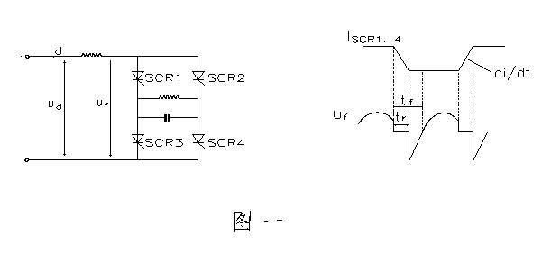
Generally, under working conditions above 400HZ, KK devices should be considered; when the frequency is above 4KHz, KA devices can be considered. Here we mainly introduce the selection of components in the parallel inverter circuit (see Figure 1).
(1) The component forward and reverse peak voltage VDRM, VRRM component forward and reverse peak voltage should be 1.5-2 times the actual maximum forward and reverse peak voltage. Assuming that the DC input voltage of the inverter is Ud and the power factor is cosψ, then:
VDRM/RRM=(1.5-2)πUd/(2cosψ)
(2) The rated on-state current IT (AV) of the component takes into account that when the component works at a higher frequency, its switching loss is very significant. The rated on-state current of the component should flow 2-3 times its effective value I according to the actual To consider, namely
IT(AV)=(2-3)I/1.57
Assuming that the inverter DC input current is Id, the selected device IT(AV) is
IT(AV)=(2-3)×Id/(1.57)
(3) Turn-off time tq In the parallel inverter circuit, the turn-off time of the KK element should be selected according to the pre-trigger time tf and the commutation time tr. Generally take:
tq=(tf-tr)×
(When the power factor is 0.8, tf is about one-tenth of the period, tr is determined by the element di/dt less than or equal to 100A/μS) When the frequency is high, the commutation time tr can be reduced and appropriately sacrificed The method of power factor increase tf to select components with appropriate tq value