
- 16
- Sep
Induction melting furnace requirements for trigger circuit
Induction melting furnace requirements for trigger circuit
The function of the trigger circuit of the induction melting furnace is to generate a gate trigger pulse that meets the requirements to ensure that the induction melting furnace changes from blocking to conducting at the required moment. Broadly speaking, the trigger circuit of induction melting furnace often also includes a phase control circuit that controls the starting time.
The trigger circuit of the induction melting furnace should meet the following requirements:
The width of the trigger pulse should ensure that the induction melting furnace can be turned on. The converter with inductive and back-EMF loads should be triggered by a wide-frequency pulse or pulse train. Wider than 30º, the three-phase fully-controlled bridge circuit should use a width of more than 60º or use double narrow pulses separated by 60º.
The trigger pulse should have sufficient amplitude. For outdoor cold occasions, the amplitude of the pulse current should be increased to 3-5 times the maximum trigger current of the device, and the steepness of the pulse front should also be increased, generally reaching 1-2A/μs.
The provided trigger pulse should not exceed the voltage, current and power rating of the gate of the induction melting furnace, and should be within the reliable trigger area of the gate volt-ampere characteristics.
It should have good anti-interference performance, temperature stability and electrical isolation from the main circuit.
The picture below shows the common trigger circuit of induction melting furnace
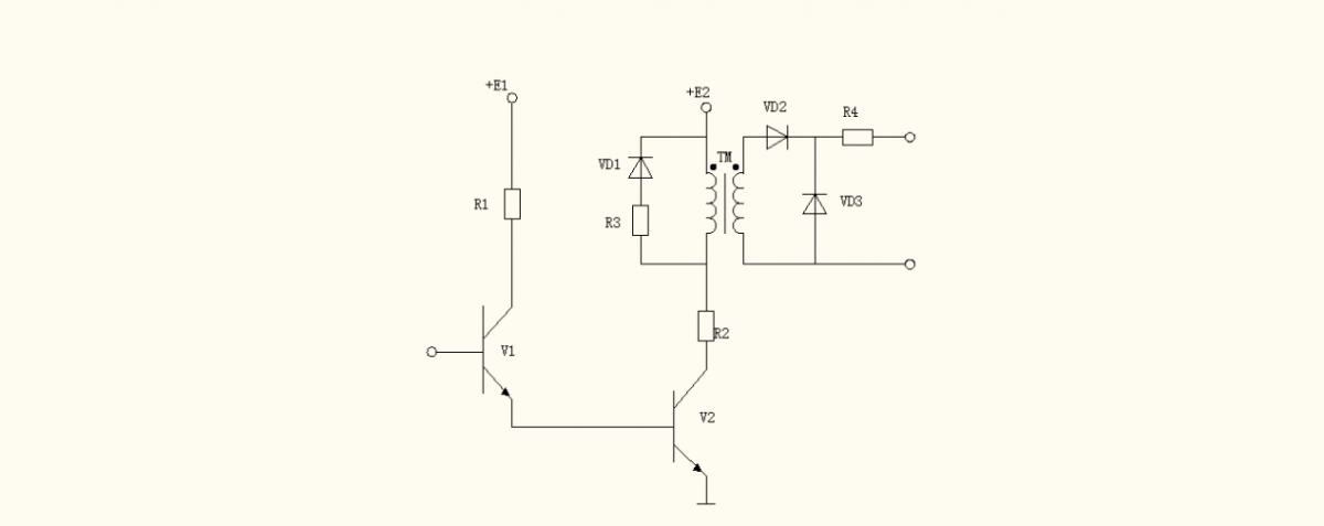
It is composed of two parts: pulse amplifying link composed of V1 and V2, and pulse counting link composed of pulse transformer TM and auxiliary circuit. When V1 and V2 are turned on, the pulse transformer is used to output a trigger pulse between the gate and the cathode of the induction melting furnace. VD1 and R3 are set for the pulse transformer TM to release its stored energy when V1 and V2 change from on to off.