- 22
- Feb
Design function and efficiency of intermediate frequency transformer
Design function and efficiency of intermediate frequency transformer
1) It has a cylindrical primary winding and a fixed transformation ratio of the outer core-shaped permeable magnet (shell type) structure. Its primary winding has a fixed number of turns, which is suitable for fixed products of special hardening machines, such as those equipped with split-and-close inductors. Crankshaft quenching machine tools, camshafts, auto flywheel ring gears and other special machine tools. Its advantages are simple structure and convenient maintenance.
2) With a multi-turn ratio outer core-shaped magnetic conductor structure with a disc-shaped primary winding, its transformation ratio can be adjusted by changing the tap plate, and its primary winding turns range is 10 to 34 turns. The secondary winding is connected to 2 turns or 1 turn through the inductor connection board. Its main advantage is that it can be adapted to the requirements of different sensor parameters through adjustment.
3) The thin intermediate frequency transformer is mainly designed for crankshaft quenching machine tools. It is characterized by a thin width and a thickness of only 62mm, which can adapt to the requirement that multiple transformers must be installed due to the close distance between the main journal and the connecting rod journal.
(3) Ferrite core quenching transformer is characterized by the use of ferrite for the magnetic core, which is generally not water-cooled, small in size and light in weight.
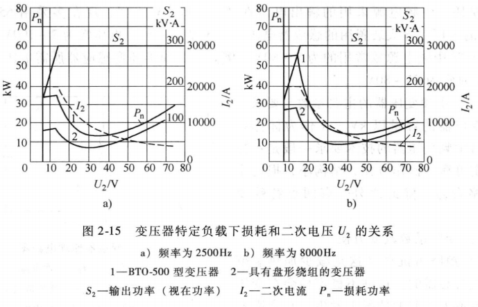
For the configuration of the intermediate frequency transformer, the capacity selection is generally considered as 3~5 times the capacity of the intermediate frequency power supply. In fact, the transformer also has a utilization factor, that is, its load factor. When the load rate is low, the capacity can be smaller, and when the load rate is high, the capacity must be larger. Another point is that when a transformer has different transformation ratios, its copper loss is also different. Figure 2-15 shows the relationship between the specific load and loss of the two transformers and the secondary voltage U2. It can be seen from the graph curve that when the secondary voltage is 30~40V, the transformer loss is the smallest.
- Intermediate frequency transformer and inductor connection Intermediate frequency transformers are used for high impedance inductors, usually 2 turns or 3 turns of secondary winding, higher impedance uses an intermediate frequency autotransformer or inductor to directly connect to the intermediate frequency power supply. Such inductors are often large-diameter multi-turn inductors.