- 07
- Feb
Installation method of induction melting furnace alarm device
Installation method of induction melting furnace alarm device
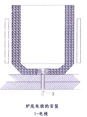
The bottom electrode of the induction melting furnace is made of φ1-2 mm non-magnetic stainless steel wire, with a total of 8-18 (depending on the size of the furnace), as shown in the figure below. The stainless steel wire is introduced through the small holes in the furnace bottom and the brick joints, and is arranged in a radial shape. The brick joints through which the steel wire passes shall be blocked and sealed with refractory mud. The stainless steel wire should have enough length. After the quartz sand layer at the bottom of the furnace is knotted, the stainless steel wire can expose the sand layer by 10-20 mm. Cut the too long part and bend it to make the exposed part and the quartz sand layer The surfaces are parallel. In this way, when the crucible is hoisted in, a good contact between the stainless steel wire and the iron crucible can be ensured. After the iron crucible is melted, the steel wire is always in contact with the iron liquid phase. When the furnace lining is repaired, the original stainless steel wire can be found in the non-sintered layer of the furnace bottom, and the stainless steel wire can be extended. The installation method is the same as the above. The stainless steel wires drawn from the small holes in the furnace bottom should be combined into one strand and covered with a heat-resistant porcelain tube to prevent the stainless steel wires from contacting the furnace bottom steel plate and cause a short circuit to the ground. Before each melting, it is necessary to check the bottom electrode stainless steel wire, liquid charge and the input end of the lining wall thickness inspection device. All four links must be in good contact. If there is any problem, it must be repaired before it can be put into work. The connection between the detection device and the furnace is: OUT (-) furnace bottom probe. OUT (+) is connected to the copper bar (or embedded steel wire in the furnace wall) connected to the induction coil after the external inductor is connected (as shown in the figure below), and the wire should be double insulated. The power cord is connected to the AC 220V power supply.

