
- 25
- Oct
Performance parameter table of epoxy glass fiber wound insulation cylinder
Performance parameter table of epoxy glass fiber wound insulation cylinder
Product use: Widely used in the main insulators of high-voltage products such as oil-immersed transformers, H-class dry-type transformers, railway locomotive transformers, on-load tap-changers, reactors, arresters, SF6 transformers, and test devices.
Features:
1. High withstand voltage
2. Low dielectric loss
3. The partial discharge is small
4. High mechanical strength
5. No deformation and no delamination
6. Very low water absorption
7. Chemical resistance (SF6 resistance)
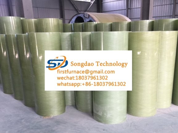
Product specifications: the inner diameter of the insulating cylinder ranges from Φ6mm to Φ2480mm, the wall thickness of the small tube is ≥0.5mm, the wall thickness of the large tube is ≥3mm, the wall thickness of the super-large tube is ≥5mm, and the length is within the length of the core mold. Our company has more than 400 sets of molds ranging from Φ6mm to Φ2480mm. (For specific specifications, please refer to the core mold specification table). Special specifications will be negotiated separately.
Order notice:
1. All users, please try to apply the existing mandrel specifications, such as the cost and time of redo mandrel.
2. Because the production process has a period of time and the specifications of each user are different, please order in advance.
Performance parameter table of Class H epoxy fiberglass insulation cylinder
| No | Indicator name | Requirements | Unit | Index value |
| 1 | Density | G/cm3 | 1.9-2.0 | |
| 2 | Intensity of bending | No less than | Mpa | 320 |
| 3 | Pressure resistance strength | No less than | Mpa | 200 |
| 4 | Anti-shear strength | No less than | Mpa | 32 |
| 5 | Medium Loss Factor (50Hz) | No greater than | 0.02 | |
| 6 | The dielectric constant | 3~6 | ||
| 7 | When the volume resistivity is normal | No less than | Qm | 10X1011 |
| After immersion | 10X109 | |||
| 8 | When the parallel layer moves toward the normal insulation resistance | No less than | Q | 10X1011 |
| After immersion | 10X109 | |||
| 9 | Surface voltage resistance
(Pressure-resistant lmin,30mm in the air) |
KV | 14 | |
| 10 | Vertical layer direction resistance voltage of 8> 3mm | KV | 20 | |
| 11 | Parallel layer-resistant voltage (25mm spacing) | No less than | KV | 50 |
| 12 | Insulation resistance | No less than | MQ | 5X10⁴ |
| 13 | Industrial frequency voltage resistance distance (by customer technology
Requirements) |
No less than | KV | 80 |
| 14 | Heat resistance | No less than | °C | 180 |
| 15 | Meverage thermal deformation temperature | No less than | °C | 250 |