
- 24
- Nov
How to debug the control panel of the intermediate frequency furnace? Detailed debugging steps
How to debug the control panel of the intermediate frequency furnace? Detailed debugging steps
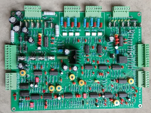
The control board of the intermediate frequency furnace is a very important component when the intermediate frequency furnace is working. From selection to circuit board welding, to debugging and aging test, it is a very important link. Among them, many users will ignore the debugging work of the control board, and they don’t know how to debug the control board of the intermediate frequency furnace. Today I summarized the relevant content of the control panel debugging steps to explain to you, let’s take a look at it together.
1. The debugging steps of the rectification part of the control panel of the intermediate frequency furnace
1. For the safety of debugging, the inverter bridge should be disabled before debugging.
2. Three-phase power supply can be supplied, regardless of the phase sequence, and check whether there is a phase failure alarm report. If so, check whether the incoming fast fuse is damaged.
3. Turn the “given” potentiometer on the panel to a large clockwise, the DC voltage waveform should be almost fully released, and all the 6 wave heads are in. If the intermediate frequency power supply is 380V input, the DC voltmeter should be an indication at this time Around 530V. Then turn the “given” potentiometer on the panel counterclockwise to small, the DC voltage waveform is almost completely closed, and the angle A is about 120 degrees at this time. The output DC waveform should be continuous and smooth in the entire phase shift range.
4. In the power failure state, connect the inverter bridge to make the inverter trigger pulse input, and remove the resistive load at the rectifier bridge port. Turn the “W1VF” trimming potentiometer on the circuit board clockwise to the end, (when the inverter overvoltage occurs during the debugging process, it can provide overvoltage protection). The switch on the main control panel is set to the ON position, and the “given” potentiometer on the panel is rotated counterclockwise.
5. After powering on for a few seconds, turn the “given” potentiometer on the panel clockwise slowly to increase. At this time, the inverter bridge will appear in two working states, one is the inverter bridge oscillating, the other is It is the inverter bridge through. What is needed at this time is the inverter bridge direct connection. If the inverter bridge is in the oscillating state, the phase of the intermediate frequency voltage transformer can be adjusted in the state of power failure, that is, the output line of the intermediate frequency voltage transformer 20V winding can be adjusted. It will start to vibrate. In the operation of slowly turning the “given” potentiometer on the large panel, pay close attention to the response of the ammeter. If the indication of the ammeter increases rapidly, you should quickly turn the “given” potentiometer counterclockwise. ,
6. At this time, it indicates that there is a problem with the current sampling circuit, and the system is in the current open loop state. Check whether the current transformer is connected. The normal performance is that as the “given” potentiometer slowly increases, the indication of the ammeter also increases. When the “given” potentiometer stops rotating, the indication of the ammeter can stably stop at a certain scale.
7. When there is a through phenomenon, turn the “given” potentiometer on the panel clockwise to make the indication of the ammeter close to about 50% of the rated value. The glue current voltmeter measures the voltage between the three terminals. The three voltages should be approximately the same. If the difference is too large, it means that the terminal with the same name of the current transformer is wrongly connected. It must be corrected, otherwise it will affect the normal operation of the current regulator. .
8. Continue to turn the “given” potentiometer on the panel clockwise to the end, the indication of the ammeter should be close to the rated value, and adjust the current on the main control board counterclockwise to feed the trimming potentiometer to make the DC ammeter indicate the rated output current. The setting of the rated current is completed. In this way, the debugging of the rectifier bridge is basically completed, and the debugging of the inverter bridge can be carried out.
9. When the power supply of the debugging site cannot supply the rated current of the device, the setting of the rated current can be carried out when the site is running at full load. However, you should first determine whether the current sampling loop is working properly under the condition of small current.
Second, the debugging steps of the inverter part of the control panel of the intermediate frequency furnace
1, calibration frequency table
DIP -2 of the switch on the main control board is set to the ON position, DIP -3 is set to the OFF position, and the “given” potentiometer on the panel is turned down counterclockwise. Connect the oscilloscope to the tube case of Q5 or Q6, measure the other excitation frequency of the inverter trigger pulse (the other excitation frequency can be adjusted by FMAX and DIP-1), adjust: W6 FHZ “fine-tune the potentiometer to make the reading of the frequency meter It is consistent with that measured by the oscilloscope. If the intermediate frequency power supply uses a special intermediate frequency frequency meter, this step of debugging can be omitted.
2, start-up inverter
(1) Firstly, check whether the gate line of the inverter thyristor is connected correctly, and whether the brightness of the LED on the last stage of the inverter is normal. If it is not bright, it means that the E and C terminals of the inverter stage are reversed; then the main control board Unplug the external connection of the upper UA, and see if the LED inverter stage that is extinguished is in the diagonal position of the inverter bridge.
(2) Turn the DIP-2 of the DIP switch on the main control board to the ON position and DIP-3 to the OFF position, turn the “given” potentiometer on the panel to the end, and adjust the “W5” on the control panel. FMAX “Fine-tuning potentiometer and DIP-1, make the excitation frequency higher than 1.4 times of tank circuit resonance frequency, “W3MAX” and “W4MIN” fine-tuning potentiometers are turned in the middle position. Turn the “given” potentiometer on the panel clockwise to a large amount, and then its excitation frequency starts to sweep from high to bottom. The inverter bridge enters the working state and starts to vibrate.
(3) If it does not vibrate, it will be shown as it stimulates the signal to perform repeated frequency sweeping actions, which can adjust the phase of the intermediate frequency voltage transformer, that is, reverse the output line of the 20V winding of the intermediate frequency voltage transformer. If the output line of the 20V winding of the intermediate frequency voltage transformer is reversed, it still fails to start. At this time, you should confirm whether the resonance frequency of the tank circuit is correct. You can use a capacitance/inductance meter to measure the capacitance of the heating capacitor and the inductance of the inductor. Calculate the resonant frequency of the tank circuit. When the resonant frequency of the tank circuit is in the range of 0.6 to 0.9 of the excitation frequency, it should be easy to start. The next step is to check whether the inverter thyristor is damaged.
3, set the front angle of the reverse lead
(1) After the inverter starts to vibrate, you can do the work of setting the front angle of the inverter. Turn the DIP switch DIP-2 in the ON position and DIP-3 in the OFF position. The pulser observes the waveform of the 100V winding of the voltage transformer and adjusts The “W4MIN” fine-tuning potentiometer on the main control board makes the inverse conversion phase lead angle around 25°. At this time, the ratio of the intermediate frequency output voltage to the DC voltage is around 1.3.
(2) Turn the DIP-3 switch to the ON position again, adjust the “W3 MAX” trimming potentiometer on the main control board, and set the front angle of the reverse conversion phase lead. According to the different intermediate frequency output voltage of 750V, the inverse conversion phase lead angle is required to be about 42°. At this time, the ratio of the intermediate frequency output voltage to the DC voltage is 1.5.
(3) If there is an excessively large front angle of the inverter during debugging, check whether the tank circuit resonance frequency is too low.
4. Setting of rated output voltage
Set the rated output voltage under light load conditions, set the DIP switch DIP-2 on the main control board to the ON position and DIP-3 to the OFF position. “Turn the potentiometer clockwise, and the inverter bridge works. Continue to turn the “given” potentiometer on the panel clockwise to increase. At this time, the output intermediate frequency voltage is close to the rated value. Adjust the “W1VF” fine-tuning potentiometer counterclockwise to make the output intermediate frequency voltage reach the rated value.