- 28
- Sep
インダクタ焼入れ用クイックチェンジチャック
インダクタ焼入れ用クイックチェンジチャック
間の接続 inductor and the quenching transformer requires strong electrical connection, low resistance, and reliability. The early design of the inductor and the transformer contact plate are connected with bolts and nut washers: the intermediate frequency sensor has two rows of M12 bolts, a total of 10 bolts; the high frequency sensor also has M8 or M10 bolts, a total of 4 bolts. It is time-consuming and laborious to load and unload the sensor once, and the cooling water inlet and outlet pipes need to be connected to the sensor, which increases the auxiliary time.
センサー用クイックチェンジチャック
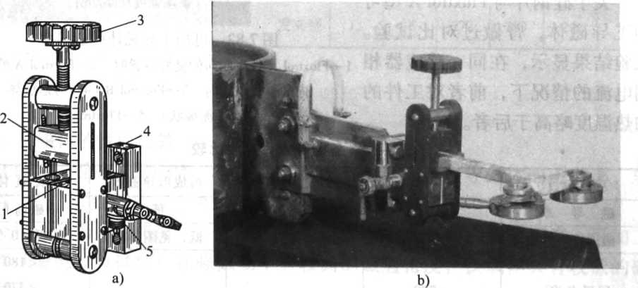
写真はセンサー用クイックチェンジチャックで、接触板本体、加圧ハンドル、加圧ブロック、シールリング、給水バルブで構成されています。 正面中央にセンサーの挿入口があり、3 つのシール リングはセンサーの水の入口と出口です。 接続ブロックの標準構造のセンサーが挿入口に入ったら、ハンドル5をひねると、ベークライトプレスブロックが接続ブロックを挿入口の底面に押し付け、水と電気の接続が一度に完了します。 センサーを交換するときは、給水バルブ 10 を閉じることができます。 この構造により、センサー交換は約60秒で作業効率が大幅に向上し、省力化が図れます。 このチャックは生産で広く使用されており、XNUMXkW未満の高周波電力により適しています。

図 センサークイックチェンジチャックとセンサー
a) クイックチェンジチャック b) センサー付きクイックチェンジチャック
1 シールリング 2 圧力ブロック 3 ハンドル 4 コンタクトプレート本体 5 水入口バルブ
