- 28
- Jun
Selection method of steel shell furnace body of induction melting furnace
Selection method of steel shell furnace body of induction melting furnace
1. Furnace
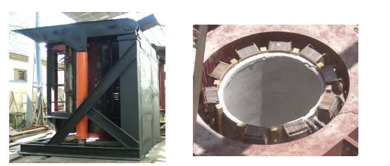
The furnace body is composed of induction coil, magnetic yoke, furnace frame, tilting cylinder and so on.
Induction coil

The induction coil is made of 99.9% rectangular copper tube. The induction coil adopts the process of wrapping mica tape and dipping insulating varnish. The surface is sprayed with a layer of gray insulating varnish, and the withstand voltage of the insulating layer is greater than 5000V.
The induction coil is fixed by a series of bolts and insulating stays welded on its outer circumference. After the coil is fixed, the error of its turn pitch is not more
than 2mm.
Both the upper and lower parts of the induction coil are equipped with stainless steel water-cooling rings, the purpose of which is to uniformly heat the furnace lining material in the axial direction and prolong the service life of the furnace lining.
At the water outlet of the induction coil, several water temperature probes are installed according to the water circuit. When the water temperature of a certain road is blocked, an alarm can be issued immediately and the intermediate frequency power supply can be automatically shut down.
1.2, yoke
The yoke is made of cold-rolled silicon steel sheet with high permeability. The thickness of the silicon steel sheet is 0.3 mm. The yoke adopts a profiling structure, and the arc of the inner arc is the same as the arc of the outer circle of the induction coil, so that the yoke can be evenly distributed on the outside of the induction coil, which restrains the radiated magnetic field of the coil to the maximum extent and reduces the external magnetic circuit Magnetoresistance.
The yoke of vulnerable parts is clamped by stainless steel plates and stainless steel clamps on both sides and fixed by welding. A cooling water pipe is welded on the stainless steel plate on both sides to cool the yoke. The cooling water pipe can withstand 0.45Mpa water pressure without leakage within 15 minutes.
After the yoke is assembled, the curvature is not more than 4mm, and the deviation between the theoretical centerline and the actual centerline is not more than 3mm.
Teflon plates and asbestos rubber plates are lined from inside to outside between the yoke and the coil. Teflon sheet has high insulation strength and high temperature resistance, and asbestos rubber sheet has high heat resistance. This ensures the insulation and heat resistance between the yoke and the coil.
Each yoke is fixed by a screw rod fixed on the furnace shell to form a uniform pushing force on the circumference of the coil, so that both the yoke and the coil are fixed, and the coil will not be generated during the melting and out of the furnace. move.
1.3. Stove
The furnace frame is divided into two parts: movable and fixed.
1.3.1, movable stove
The movable furnace frame is used to install the induction coil and the magnetic yoke. It is welded by section steel and steel plate, and adopts a frame structure for easy maintenance. The operating platform on the top of the movable grate adopts thickened steel plates to improve the strength and load-bearing capacity of the grate.
1.3.2, fixed hob
The fixed furnace frame is installed on the foundation to carry the movable furnace frame. The upper part of the fixed grate is connected to the movable grate through a tilting shaft, and the movable grate can be tilted forward by 95 degrees under the push of the tilting oil cylinder.
A great safety factor is reserved in the design of the grate part. Ensure that the furnace frame has sufficient rigidity and runs smoothly when carrying the maximum load.
1.4 Furnace cover
A furnace cover is installed on the movable furnace frame. The furnace cover can be operated manually and hydraulically.
1.4.1, manual furnace cover
The manual furnace cover is installed on the rotating shaft on the upper side of the furnace body, and the furnace cover can be opened and closed by moving the handle up and down. When charging or not needing to use the furnace cover, the furnace cover can be rotated to the side position of the upper part of the furnace body.
1.4.2. Hydraulically driven furnace cover:
The hydraulically driven furnace cover is installed on the rotating shaft on the upper side of the furnace body, and the opening and rotation of the furnace cover are realized through the actions of the upper and lower oil cylinders and the rotating oil cylinder. Operate through the operation switch on the console. When charging or not needing to use the furnace cover, the furnace cover can be rotated to the side position of the upper part of the furnace body.
