
- 21
- Sep
Gangdi coreless induction furnace technical description
Gangdi coreless induction furnace technical piav qhia
In recent years, large-capacity steel shell coreless induction furnaces manufactured by foreign induction heating companies have made great improvements in the structure of the furnace body. Figure 12-83 is a cross-sectional view of a steel shell coreless induction furnace.
The steel shell coreless induction furnace is compared with the previously produced steel frame coreless induction furnace. Because the furnace shell is rolled by thick steel plate, it provides strength for the entire furnace body. The permeable magnet is directly fixed on the steel shell and provides strong support for the induction coil. During the tilting of the furnace, all the weight is carried on the steel shell. Even if the overhaul hole on the steel shell is large, the furnace body has strong strength and avoids the deformation caused by the tilting of the furnace.
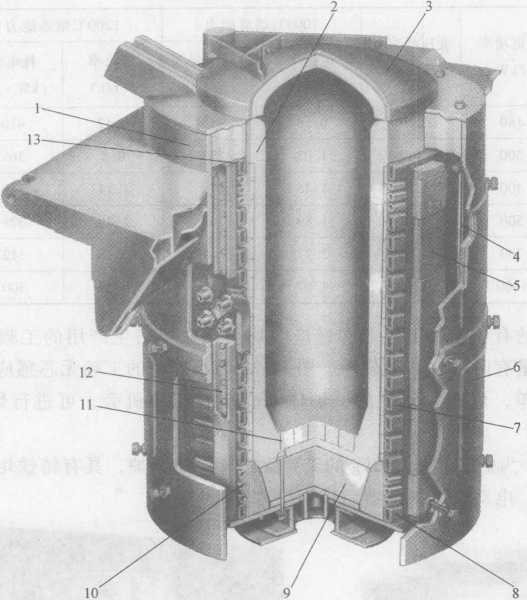
Figure 12-83 The furnace body of the heavy steel shell furnace
1 a furnace shell 2 a smashed furnace lining 3 a furnace cover 4 a tie rod 5-a magnet
6—overhaul hole cover 7—induction coil 8—water-cooled pure copper ring 9 a special-shaped refractory brick
10—Water cooling pipe 11—Earth leakage protection device 12—Bakelite column 13—heat-resistant insulation board
The service life of the furnace lining can be prolonged. Since the steel shell is closed and the induction coil is enclosed, the working noise is greatly reduced during smelting, and the splashed metal cannot touch the induction coil, completely avoiding the damage to the induction coil.
The induction coil is wound by a rectangular thick-walled pure copper tube with a certain gap between the turns. The pure copper tube is welded with a stud to be fixed with the bakelite column to ensure the inter-turn gap size of the coil. The coil is not easy to be deformed, and the inter-turn gap of the coil can make the water vapor in the lining material volatilize easily. There are water-cooled pipes wound with stainless steel pipes at both ends of the coil, which can not only achieve the purpose of uniform furnace lining temperature, but also reduce thermal expansion. On the top and bottom of the coil, there is a water-cooled pure copper ring, which generates a reverse magnetic flux during operation, which reduces the demagnetization at both ends of the coil and avoids heating of the steel shell. The coil compression device prevents vibration. It used to be a spring structure, but now it is replaced by an easy-to-adjust pull rod. The permeable body is arc-shaped and can fit well with the coil. An insulating spacer is placed between the permeable magnet and the coil to reduce noise and vibration. There is a thick aluminum plate at the bottom of the furnace to avoid heating at the bottom of the furnace, and the bottom of the furnace is open, easy to ventilate, to avoid accumulation of moisture, and in case of furnace leakage, it can also reduce the degree of damage.
Figure 12-84 shows the compressed arc-shaped magnetic conductor, the pressure plate made of non-magnetic stainless steel, welded together with the silicon steel sheet. The magnetic conductor used before has holes punched in the silicon steel sheet. After the silicon steel sheet is laminated, it is compressed with non-magnetic stainless steel bolts and nuts, and it is impossible to make it into an arc shape.
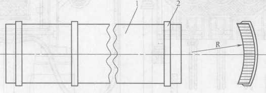
Figure 12-84 Compact permeable magnet
1—Silicon steel sheet 2—Press plate