
- 11
- Feb
Method for induction heat treatment of steel strip
Method for induction heat treatment of steel strip
According to the requirements of use, the steel belt must have both wear resistance and good toughness, so the steel belt must be heat treated in order to obtain good overall performance. Figure 12-59 is a schematic diagram of the induction heat treatment equipment for steel strip. The steel strip is heated to the quenching temperature by the first inductor, and is quenched by the nozzle 7; the second inductor 8 is tempered and heated, and then air-cooled. When the steel strip is cooled below 200°C, the nozzle 10 sprays water for rapid Cool to room temperature.
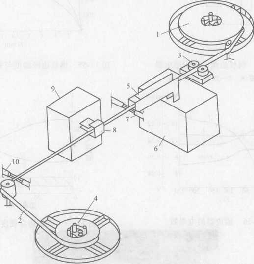
Figure 12-59 Steel strip induction heat treatment equipment
1—Send reel 2-Steel belt 3-Guide wheel 4- Take-up reel 5—Quenching heating inductor
6-Inverter 7—Nozzle 8-Temp heating sensor 9-Inverter 10—Nozzle
For a standard size steel belt used as a band saw, its moving speed can exceed 8m/min, and the power of the high-frequency generator is 10-30kW.
When the steel strip sent out by the reel has cut serrations, a serrated tip quenching equipment can be placed between the nozzle 10 and the take-up reel 4. The quenching equipment includes an inductor 11 and a quenching nozzle 13 (see Figure 12- 60) The sensor 11 heats the serration tip at a temperature higher than the Curie point, and heats the recessed part between the two teeth at a temperature lower than the Curie point. The hardness of the serration tip can reach 65RC, and it is recessed between two consecutive teeth. The hardness of the part is maintained at the hardness after tempering in the inductor 8.
In some cases, when passing through the sensor 11 and entering the nozzle 13, the steel strip is slightly deformed. In order to avoid this deformation, the sensor 14 is installed on the opposite side of the sensor 11 to be lower than the Curie point. The temperature of the saw blade on the opposite side of the tooth is heated.
The frequency of the generator supplied for quenching heating should be higher than the frequency of the current used for tempering heating.
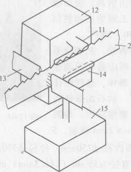
Figure 12-60 Steel band saw tooth induction heating quenching
H—Inductor 12—Inverter 13—Quenching nozzle 14—Inductor 15—Inverter