- 28
- Dec
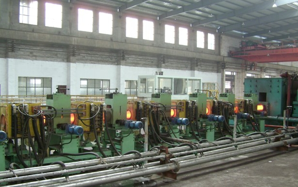
Working principle of sucker rod heat treatment line
Working principle of sucker rod heat treatment line
1. رف التغذية على خط المعالجة الحرارية لقضيب المصاص (بما في ذلك جهاز تجميع السوائب ومغذي القرص): رف التغذية مخصص لتكديس الأنابيب الفولاذية للتسخين ، والرف مصنوع من صفيحة فولاذية بسمك 16 مم و 20 # ، مدلفن على الساخن I – على شكل مصنوع من الفولاذ الملحوم ، وعرض الطاولة 200 مم ، ومنحدر المنضدة 3 درجات ، ويمكن وضع 20 × 159 أنبوبًا فولاذيًا. المنصة والعمود ملحومان ، ويتم رفع مجموعة المواد بالكامل على المنصة بواسطة رافعة أثناء العمل ، ويتم فك الحزمة يدويًا. يتم تشغيل جهاز البالات السائبة بواسطة أسطوانة هواء. طالما يتم تشغيل الأمر ، سيتم فتح دعامة البالات السائبة ، وسوف يتدحرج الأنبوب الفولاذي إلى وحدة تغذية القرص لتثبيته. تم تجهيز وحدة التغذية بالقرص بإجمالي 7 وحدات إعادة تدوير للقرص على نفس المحور. بمجرد إعطاء التعليمات ، يحتاج الأنبوب الفولاذي إلى التسخين ، وسوف يتدحرج تلقائيًا إلى نهاية الطاولة وفقًا للضربات (أي الوقت). توقف في الوضع الأوسط.
2. Feeding and flipping mechanism of sucker rod heat treatment line: The feeding and flipping mechanism is the same as the lever type flipping machine. The purpose is to transfer the workpiece from this station to another, but the structure is fundamentally different. The working principle is There is a big difference, the flip mechanism is to hold the material smoothly, and then put the material down steadily, with good centering and no impact or impact. There are 9 flippers, all of which are arranged, and the working surface is inclined 3° from high to low. Driven by φ250 by 370 stroke cylinder, when the working pressure is 0.4Mpa, the pulling force is 1800kg, which is 3 times of the heaviest steel pipe. The flip and flip are connected by connecting rods and tie rods with hinges, and 9 flips are working. Simultaneous rise and fall, good synchronization.
3. نظام ناقل أسطواني على شكل V لخط المعالجة الحرارية لقضيب المصاص:
3.1. The roller conveying system is composed of 121 sets of independently driven V-shaped rollers. There are 47 V-shaped rollers on the quenching and normalizing line, 9 sets of fast-feeding V-shaped rollers (including inverter), 24 sets of heating spray V-shaped rollers (including inverter), and 12 sets of quick-lift rollers (including inverter) ). The power is driven by a cycloid pinwheel reducer, the model is XWD2-0.55-57, the speed of the quick-lift roller is 85.3 rpm, the forward speed is 50889 mm/min, and the steel pipe is transmitted in 19.5 seconds to reach the end point. There are 37 sets of tempering line, 25 sets of heating V-shaped rollers (including frequency converter), 12 sets of quick-lift rollers (including frequency converter), and the power adopts cycloidal pinwheel reducer, model XWD2-0.55-59, quick-lift The rotation speed of the roller is 85.3 rpm, the forward speed is 50889 mm/min, and the steel pipe reaches the end point in 19.5 seconds. There are V-shaped rollers between the two cooling beds, all of which are fast rollers. The V-shaped rollers are installed on three production lines and arranged at 15° on the same center. The distance between the V-shaped roller and the V-shaped roller is 1500mm, and the diameter of the V-shaped roller is φ190mm. Except for the V-shaped roller at the feed end (the feed end is cold material), all other V-shaped roller rotating shafts are equipped with cooling water devices. The supporting roller adopts an outer spherical bearing with a vertical seat. Variable frequency motor speed control, equipped with frequency converter, the speed adjustment range is 38.5 revolutions/min~7.5 revolutions/min. The conveying forward speed is 22969mm/min~4476mm/min, and the steel pipe rotation range is: 25.6 revolutions/min~2.2 revolutions/min.
3.2. The sucker rod heat treatment line is calculated according to the annual output requirements. If the output per hour is 12.06 tons, the steel pipe advance speed is 21900mm/min~4380mm/min.
3.3 النتيجة: سرعة تقدم التصميم للمخطط تفي بمتطلبات الإنتاج.
3.4. The speed of the frequency conversion motor is controlled by the frequency converter, and the time is about 3 seconds to connect the steel pipe end to end. 2.3.5 The steel pipe after normalizing and quenching enters another station smoothly. When the end of the steel pipe leaves the last spray ring, the head of the steel pipe enters the quick-lift raceway. The frequency converter controls the steel pipes that are connected end to end for about one second to separate automatically and reach the end to enter the next station.
3.6 يمكن أن يدخل الأنبوب الفولاذي بعد التطبيع والتقسية إلى سرير التبريد في الوقت المناسب. عندما تغادر نهاية الأنبوب الفولاذي مخرج القسم الأخير من المستشعر ، يدخل رأس الأنبوب الفولاذي مجرى الرفع السريع ، ويتحكم محول التردد في نهاية ونهاية الأنبوب الفولاذي لمدة ثانية واحدة تقريبًا. ينفصل بسرعة ، ويصل إلى النهاية ، ويدخل إلى سرير التبريد من خلال آلية الوجه.
3.7 بكرة الضغط العائمة: يتم دمج أسطوانة الضغط العائم وأسطوانة النقل على شكل V معًا ، ويتم تثبيت الطرف الأمامي لكل مجموعة من أجهزة الاستشعار كمجموعة. 4 مجموعات من التطبيع والتبريد ، 3 مجموعات من التقسية ، 7 مجموعات في المجموع. نظرًا لسرعة النقل السريع ، تم ضبطه لمنع الأنبوب الفولاذي من إتلاف المستشعر بسبب الارتداد الشعاعي. يمكن تعديل أسطوانة الضغط العائمة ، والمدى مناسب لأنابيب فولاذية بمواصفات مختلفة. الفجوة بين الأنبوب الفولاذي والعجلة العلوية هي 4-6 مم ، والتي يمكن تعديلها يدويًا.
3.8 جهاز تحريك مستشعر التقسية: عندما يتم تطبيع الأنبوب الفولاذي ، من أجل جعل الأنبوب الفولاذي يدخل بسلاسة إلى سرير التبريد ، يجب سحب مستشعر التقسية من خط الإنتاج. تقوم ثلاث مجموعات من الأسطوانات φ100 × 1000 بتمرير مستشعرات التقسية المتصلة عبر المسار وتنسحب من خط الإنتاج. لا يلزم تعديل السكتة الدماغية ، ودفعها للأمام ، ويكون مركز المسار هو مركز المستشعر.