
- 27
- Oct
How to detect SCR?
How to detect SCR?
Thyristor is the abbreviation for silicon controlled rectifier. There are several types of SCRs: one-way, two-way, turn-off and light-controlled. It has the advantages of small size, light weight, high efficiency, long life, convenient control, etc. It is widely used in various automatic control and high-power electric energy conversion occasions such as controllable rectification, voltage regulation, inverter, and non-contact switch. .
SCR conduction conditions: one is that a forward voltage must be applied between the anode and cathode of the thyristor, and the other is that a forward voltage must be applied to the control electrode. The above two conditions must be met at the same time, the thyristor will be in the conducting state. In addition, once the thyristor is turned on, even if the gate voltage is reduced or the gate voltage is removed, the thyristor is still turned on. SCR turn-off conditions: reduce or remove the forward voltage between the SCR anode and the cathode, so that the anode current is less than the minimum maintenance current.
1. The characteristics of thyristor:
The thyristor is divided into one-way thyristor and two-way thyristor.
The unidirectional thyristor has three lead pins: anode A, cathode K, and control electrode G.
The triac has a first anode A1 (T1), a second anode A2 (T2), and a control electrode G three lead pins.
Only when a positive voltage is applied between the unidirectional SCR anode A and the cathode K, and the required forward trigger voltage is applied between the control electrode G and the cathode, can it be triggered to conduct. At this time, there is a low-resistance conduction state between A and K, and the voltage drop between anode A and cathode K is about 1V. After the one-way SCR is turned on, even if the controller G loses the trigger voltage, as long as the positive voltage is maintained between the anode A and the cathode K, the one-way SCR continues to be in a low-resistance conduction state. Only when the anode A voltage is removed or the voltage polarity between anode A and cathode K is changed (AC zero crossing), the unidirectional thyristor will switch from a low-resistance conduction state to a high-resistance cut-off state. Once the unidirectional thyristor is cut off, even if the positive voltage is reapplied between the anode A and the cathode K, a positive trigger voltage must be reapplied between the control electrode G and the cathode K to be turned on. The on and off state of the one-way SCR is equivalent to the on and off state of the switch, and it can be used to make a non-contact switch.
Between the first anode A1 and the second anode A2 of the bidirectional thyristor, regardless of whether the applied voltage polarity is forward or reverse, as long as the trigger voltage with different positive and negative polarity is applied between the control electrode G and the first anode A1, it can be The trigger conduction is in a low-impedance state. At this time, the voltage drop between A1 and A2 is also about 1V. Once the triac is turned on, it can continue to be turned on even if the trigger voltage is lost. Only when the current of the first anode A1 and the second anode A2 decreases and is less than the maintenance current or when the voltage polarity between A1 and A2 changes and there is no trigger voltage, the triac will be cut off. At this time, the trigger voltage can only be reapplied. Conduction.
2. Pagkakita sa us aka paagi nga SCR:
The multimeter selects the resistance R*1Ω, and the red and black test leads are used to measure the forward and reverse resistance between any two pins until a pair of pins with a reading of tens of ohms is found. At this time, the pin of the black test lead is the control electrode G , The pin of the red test lead is the cathode K, and the other free pin is the anode A. At this time, connect the black test lead to the judged anode A, and the red test lead to the cathode K. The pointer of the multimeter should not move at this time. Use a short wire to instantaneously connect anode A and control electrode G. At this time, the multimeter electric blocking pointer should be deflected to the right, and the resistance reading is about 10 ohms. If the anode A is connected to the black test lead and the cathode K is connected to the red test lead, the pointer of the multimeter will deflect, indicating that the one-way SCR has been broken down and damaged.
3. Pagpangita Triac:
Use the multimeter resistance R*1Ω block, use the red and black meter pens to measure the positive and negative resistance between any two pins, and the results of the two sets of readings are infinite. If one set is tens of ohms, the two pins connected to the set of red and black watches are the first anode A1 and the control electrode G, and the other free pin is the second anode A2. After determining the A1 and G poles, carefully measure the positive and reverse resistances between the A1 and G poles. The pin connected to the black test lead with the relatively small reading is the first anode A1, and the pin connected to the red test lead is Control pole G. Connect the black test lead to the determined second anode A2 and the red test lead to the first anode A1. At this time, the pointer of the multimeter should not be deflected, and the resistance value is infinite. Then use a short wire to short the A2 and G poles instantaneously, and apply a positive trigger voltage to the G pole. The resistance between A2 and A1 is about 10 ohms. Then disconnect the short wire between A2 and G, and the multimeter reading should keep about 10 ohms. Interchange the red and black test leads, connect the red test lead to the second anode A2, and the black test lead to the first anode A1. Similarly, the pointer of the multimeter should not be deflected, and the resistance should be infinite. Use a short wire to short-circuit the A2 and G poles again instantly, and apply a negative trigger voltage to the G pole. The resistance between A1 and A2 is also about 10 ohms. Then disconnect the short wire between the A2 and G poles, and the multimeter reading should remain unchanged at about 10 ohms. In accordance with the above rules, it indicates that the tested triac is not damaged and the polarity of the three pins is judged correctly.
When detecting high-power SCRs, a 1.5V dry battery needs to be connected in series with the black pen of the multimeter to increase the trigger voltage.
4. Pin identification of thyristor (SCR):
The judgment of the thyristor pins can be done in the following ways: First, measure the resistance between the three pins with a multimeter R*1K. The two pins with the smaller resistance are the control electrode and the cathode, and the remaining pin is the anode. Then put the multimeter in the R*10K block, pinch the anode and the other leg with your fingers, and do not let the two feet touch, connect the black test lead to the anode, and the red test lead to the remaining leg. If the needle swings to the right, it means the red test lead Connected as the cathode, if it does not swing, it is the control electrode.
The unidirectional thyristor is composed of three PN junction semiconductor materials, and its basic structure, symbol and equivalent circuit are shown in Figure 1.
Thyristor has three electrodes: anode (A), cathode (K) and control electrode (G). From the equivalent circuit point of view, the anode (A) and the control electrode (G) are two PN junctions connected in series with opposite polarities, and the control electrode (G) and the cathode (K) are a PN junction. According to the unidirectional conductivity characteristics of the PN junction, select the appropriate resistance file of the pointer multimeter, and test the positive and negative resistance between the poles (the same two poles, exchange the two resistance values measured by the test pen). For the normal thyristor, G The forward and reverse resistances between G and K are very different; the forward and reverse resistances between G and K and A are very small, and their resistance values are very large. This test result is unique, and the polarity of the thyristor can be determined based on this uniqueness. Use a multimeter to measure the forward and reverse resistances between the SCR electrodes in the R×1K file, and select the two electrodes with a large difference in forward and reverse resistance. For the control electrode (G), the red test lead is connected to the cathode (K), and the remaining electrode is the anode (A). By judging the polarity of the thyristor, the quality of the thyristor can also be determined qualitatively. If the difference between the forward and reverse resistances of any two poles in the test is very small, and the resistance values are very large, it indicates that there is an open-circuit fault between G and K; if the forward and reverse resistances between the two poles are very small and approaching At zero, there is an inter-electrode short-circuit fault inside the SCR.

One-way SCR trigger characteristic test:
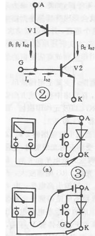
The one-way thyristor is the same in that both have unidirectional conductivity, but the difference is that the conduction of the thyristor is also controlled by the voltage of the gate. That is to say, two conditions must be met for the thyristor to be turned on: a positive voltage should be applied between the anode (A) and the cathode (K), and a forward voltage should also be applied between the control electrode (G) and the cathode (K) . When the thyristor is turned on, the control electrode loses its function. The conduction process of the unidirectional thyristor can be illustrated by the equivalent circuit shown in Figure 2: The emitter of the PNP tube is equivalent to the anode of the thyristor (A), and the emitter of the NPN tube is equivalent to the cathode of the thyristor (K) , The collector of the PNP tube is connected to the base of the NPN tube, which is equivalent to the control electrode (G) of the thyristor. When the allowable forward voltage is applied between A and K, the two tubes will not conduct. At this time, when the forward voltage is applied between G and K, the base of the control current flowing into V2 is formed, and so on. Until the two tubes are fully connected. When turned on, even if Ig=O, because V2 has a base current and is much larger than Ig, the two tubes are still turned on. To make the conductive thyristor cut off, the forward voltage of A and K must be reduced to a certain value, or reversed, or disconnected. According to the conductive characteristics of the SCR, the resistance file of a multimeter can be used for testing. For low-power thyristor, connect the circuit as shown in Figure 3(a), connect a touch switch between thyristor A and G (for ease of operation), use the R×1Ω gear of the multimeter, and connect the black test lead. A pole, the red test lead is connected to K. At this time, a positive voltage is applied to the thyristor (through the dry battery attached to the multimeter). The pointer of the multimeter does not move and the thyristor does not conduct. When the switch is pressed, A, G When the trigger voltage is applied between G and K, the thyristor is turned on, and the pointer of the multimeter deflects and points to a smaller value; when G and A are disconnected, the control voltage is lost. If the pointer of the multimeter If the position remains unchanged, the thyristor is still in the conducting state, indicating that the triggering characteristics of the thyristor are good. If G and A are disconnected, the pointer of the multimeter will be deflected and point to ∞. That is, if the thyristor is not conducting, it indicates that the triggering characteristic of the thyristor is not good or has been damaged. For thyristors with higher power, due to the large turn-on voltage drop, the maintenance current is difficult to maintain, causing the conduction state to be poor. At this time, a dry battery should be connected in series to the anode (A) of the thyristor, as shown in the figure. The circuit shown in 3(b) should be tested to avoid misjudgment. For high-power thyristor, a dry cell should be connected in series on the circuit of Figure 3(b) to make the test effect obvious. Generally speaking, when testing one-way SCRs below 10A, use the connection circuit shown in Figure 3(a); for 10A-100A SCRs, use the connection circuit shown in Figure 3(b) to test the one-way controllable above 100A.
On the basis of testing one-way thyristors, other types of thyristors can also be tested with a multimeter according to their basic structure.