
- 27
- Oct
SCR ကို ဘယ်လိုဖော်ထုတ်မလဲ။
SCR ကို ဘယ်လိုဖော်ထုတ်မလဲ။
သီရိ is the abbreviation for silicon controlled rectifier. There are several types of SCRs: one-way, two-way, turn-off and light-controlled. It has the advantages of small size, light weight, high efficiency, long life, convenient control, etc. It is widely used in various automatic control and high-power electric energy conversion occasions such as controllable rectification, voltage regulation, inverter, and non-contact switch. .
SCR conduction အခြေအနေများ- တစ်ခုကတော့ thyristor ၏ anode နှင့် cathode အကြား forward voltage ကို အသုံးချရမည် ဖြစ်ပြီး နောက်တစ်ချက်မှာ control electrode သို့ forward voltage ကို သက်ရောက်စေရမည် ဖြစ်သည်။ အထက်ဖော်ပြပါ အခြေအနေနှစ်ခုကို တစ်ချိန်တည်းတွင် လိုက်လျောညီထွေဖြစ်ရမည်၊ thyristor သည် conducting အခြေအနေတွင် ရှိနေမည်ဖြစ်သည်။ ထို့အပြင်၊ thyristor ကိုဖွင့်လိုက်သည်နှင့်၊ ဂိတ်ဗို့အားလျော့သွားသည် သို့မဟုတ် gate voltage ကိုဖယ်ရှားလိုက်လျှင်ပင် thyristor ကိုဖွင့်ထားဆဲဖြစ်သည်။ SCR အဖွင့်အပိတ်အခြေအနေများ- SCR anode နှင့် cathode အကြားရှေ့ဆက်ဗို့အားကို လျှော့ချရန် သို့မဟုတ် ဖယ်ရှားပါ၊ သို့မှသာ anode သည် အနိမ့်ဆုံးပြုပြင်ထိန်းသိမ်းထားသော လက်ရှိထက်နည်းနေစေရန်။
1. thyristor ၏လက္ခဏာများ-
သိုင်းရစ်စတာကို တစ်လမ်းသွား သိုင်းရစ်စတာနှင့် နှစ်လမ်း သိုင်းရစ်စတာဟူ၍ ပိုင်းခြားထားသည်။
unidirectional thyristor တွင် ခဲတံသုံးခုပါရှိသည်- anode A၊ cathode K နှင့် control electrode G။
triac တွင် ပထမ anode A1 (T1)၊ ဒုတိယ anode A2 (T2) နှင့် control electrode G ခဲတံသုံးခုရှိသည်။
unidirectional SCR anode A နှင့် cathode K အကြား အပြုသဘောဆောင်သော ဗို့အားကို သက်ရောက်ပြီး လိုအပ်သော ရှေ့ထရစ်ဆာဗို့အားကို ထိန်းချုပ်လျှပ်ကူးပစ္စည်း G နှင့် cathode ကြားတွင် သက်ရောက်မှသာ လုပ်ဆောင်နိုင်မည်ဖြစ်သည်။ ယခုအချိန်တွင် A နှင့် K အကြား ခုခံမှုနည်းသော conduction အခြေအနေရှိပြီး anode A နှင့် cathode K အကြား ဗို့အားကျဆင်းမှုသည် 1V ခန့်ဖြစ်သည်။ တစ်လမ်းသွား SCR ကိုဖွင့်ပြီးနောက်၊ controller G သည် trigger voltage ဆုံးရှုံးသွားသော်လည်း anode A နှင့် cathode K ကြားတွင် positive voltage ကို ထိန်းသိမ်းထားသရွေ့၊ one-way SCR သည် ခုခံမှုနည်းသောနေရာတွင် ဆက်လက်ရှိနေပါသည်။ conduction အခြေအနေ။ anode A ဗို့အားကို ဖယ်ရှားလိုက်သည့်အခါ သို့မဟုတ် anode A နှင့် cathode K အကြား ဗို့အားဝင်ရိုးစွန်းကို ပြောင်းလဲသွားသောအခါမှသာ (AC သုညဖြတ်ကူးခြင်း)၊ unidirectional thyristor သည် ခုခံမှုနည်းသော conduction အခြေအနေမှ ခုခံမှုမြင့်မားသော cut-off အခြေအနေသို့ ပြောင်းလဲသွားမည်ဖြစ်သည်။ unidirectional thyristor ကိုဖြတ်လိုက်သည်နှင့် anode A နှင့် cathode K အကြားအပြုသဘောဗို့အားကိုပြန်လည်အသုံးချပါက၊ ဖွင့်ရန်အတွက် control electrode G နှင့် cathode K အကြားအပြုသဘောဆောင်သောဗို့အားကိုပြန်လည်အသုံးချရမည်ဖြစ်သည်။ တစ်လမ်းမောင်း SCR ၏ အဖွင့်အပိတ် အခြေအနေသည် ခလုတ်၏ အဖွင့်အပိတ် အခြေအနေနှင့် ညီမျှပြီး အဆက်အသွယ်မရှိသော ခလုတ်တစ်ခု ပြုလုပ်ရန် အသုံးပြုနိုင်သည်။
ထိန်းချုပ်လျှပ်ကူးပစ္စည်း G နှင့် ပထမ anode အကြား ကွဲပြားသော အပြုသဘောနှင့် အနုတ်သဘောဆောင်သော ဗို့အားကို သက်ရောက်နေသမျှကာလပတ်လုံး အသုံးပြုထားသော ဗို့အားဝင်ရိုးစွန်းသည် ရှေ့သို့ပြောင်းပြန်ဖြစ်စေ မသက်ဆိုင်ဘဲ ပထမ anode A1 နှင့် ဒုတိယ anode A2 အကြား၊ A1၊ ၎င်းသည် trigger conduction သည် low-impedance အခြေအနေတွင် ရှိနေနိုင်သည်။ ယခုအချိန်တွင် A1 နှင့် A2 အကြား ဗို့အားကျဆင်းမှုသည် 1V ခန့်ဖြစ်သည်။ triac ကိုဖွင့်ပြီးသည်နှင့် trigger ဗို့အားပျောက်ဆုံးသွားလျှင်ပင်၎င်းကိုဆက်လက်ဖွင့်နိုင်သည်။ ပထမ anode A1 နှင့် ဒုတိယ anode A2 ၏ လျှပ်စီးကြောင်း လျော့နည်းသွားပြီး ပြုပြင်ထိန်းသိမ်းမှု လက်ရှိထက် နည်းသွားသောအခါ သို့မဟုတ် A1 နှင့် A2 အကြား ဗို့အားဝင်ရိုးစွန်းကို ပြောင်းလဲကာ အစပျိုးဗို့အားမရှိသည့်အခါမှသာ triac ကို ဖြတ်တောက်မည်ဖြစ်သည်။ ဤအချိန်တွင်၊ အစိုင်ယာဗို့အားကိုသာ ပြန်လည်အသုံးချနိုင်သည်။ ဆောင်ခြင်း။
တစ်လမ်းသွား SCR ၏ထောက်လှမ်းခြင်း
multimeter သည် ခုခံအား R*1Ω ကို ရွေးချယ်ပြီး အနီရောင်နှင့် အနက်ရောင် စမ်းသပ်မှု ခဲများကို မည်သည့် pins နှစ်ခုကြားတွင်မဆို ရှေ့နှင့်နောက်ပြန် ခုခံမှုကို တိုင်းတာရန်အတွက် အသုံးပြုပြီး pins တစ်စုံသည် ohms ဆယ်ဂဏန်းကို ဖတ်ပြသည့်တိုင် တွေ့ရှိရသည်။ ယခုအချိန်တွင် black test lead ၏ pin သည် control electrode G ဖြစ်ပြီး အနီရောင် test lead ၏ pin သည် cathode K ဖြစ်ပြီး အခြား free pin သည် anode A ဖြစ်သည် ။ ယခုအချိန်တွင် black test lead ကို ချိတ်ဆက်ပါ။ anode A ကို စီရင်ပြီး အနီရောင် စမ်းသပ်မှုသည် cathode K သို့ ဦးတည်သည်။ multimeter ၏ pointer သည် ယခုအချိန်တွင် မရွေ့သင့်ပါ။ anode A နှင့် control electrode G ကို ချက်ခြင်းချိတ်ဆက်ရန် ဝါယာတိုတိုကို အသုံးပြုပါ။ ဤအချိန်တွင် multimeter လျှပ်စစ်ပိတ်ဆို့ခြင်းညွှန်ပြချက်ကို ညာဘက်သို့ လှန်ထားသင့်ပြီး ခံနိုင်ရည်အား 10 ohms ခန့်ရှိသည်။ anode A သည် black test lead နှင့် ချိတ်ဆက်ထားပြီး cathode K သည် အနီရောင် test lead နှင့် ချိတ်ဆက်ပါက၊ multimeter ၏ pointer သည် one-way SCR ပြိုကျပျက်စီးသွားကြောင်း ညွှန်ပြနေပါသည်။
3. Triac ထောက်လှမ်းခြင်း
Use the multimeter resistance R*1Ω block, use the red and black meter pens to measure the positive and negative resistance between any two pins, and the results of the two sets of readings are infinite. If one set is tens of ohms, the two pins connected to the set of red and black watches are the first anode A1 and the control electrode G, and the other free pin is the second anode A2. After determining the A1 and G poles, carefully measure the positive and reverse resistances between the A1 and G poles. The pin connected to the black test lead with the relatively small reading is the first anode A1, and the pin connected to the red test lead is Control pole G. Connect the black test lead to the determined second anode A2 and the red test lead to the first anode A1. At this time, the pointer of the multimeter should not be deflected, and the resistance value is infinite. Then use a short wire to short the A2 and G poles instantaneously, and apply a positive trigger voltage to the G pole. The resistance between A2 and A1 is about 10 ohms. Then disconnect the short wire between A2 and G, and the multimeter reading should keep about 10 ohms. Interchange the red and black test leads, connect the red test lead to the second anode A2, and the black test lead to the first anode A1. Similarly, the pointer of the multimeter should not be deflected, and the resistance should be infinite. Use a short wire to short-circuit the A2 and G poles again instantly, and apply a negative trigger voltage to the G pole. The resistance between A1 and A2 is also about 10 ohms. Then disconnect the short wire between the A2 and G poles, and the multimeter reading should remain unchanged at about 10 ohms. In accordance with the above rules, it indicates that the tested triac is not damaged and the polarity of the three pins is judged correctly.
စွမ်းအားမြင့် SCRs များကို ရှာဖွေတွေ့ရှိသောအခါ၊ 1.5V ခြောက်သွေ့သောဘက်ထရီကို အစပျိုးဗို့အားတိုးမြှင့်ရန်အတွက် multimeter ၏အနက်ရောင်ဘောပင်ဖြင့် အစီအရီချိတ်ဆက်ရန်လိုအပ်သည်။
4. thyristor (SCR) ကို ပင်ထိုးသတ်မှတ်ခြင်း-
thyristor pins များကို အောက်ပါနည်းလမ်းများဖြင့် စီရင်ဆုံးဖြတ်နိုင်သည်- ပထမဦးစွာ၊ multimeter R*1K ဖြင့် pin သုံးခုကြားရှိ ခံနိုင်ရည်အား တိုင်းပါ။ သေးငယ်သောခုခံမှုရှိသော pin နှစ်ခုသည် control electrode နှင့် cathode ဖြစ်ပြီး ကျန် pin သည် anode ဖြစ်သည်။ ထို့နောက် multimeter ကို R*10K ဘလောက်တွင်ထည့်ပါ၊ anode နှင့် အခြားခြေထောက်ကို သင့်လက်ချောင်းများဖြင့် ဖိကာ ခြေနှစ်ချောင်းကို မထိမိပါစေနှင့်၊ အနက်ရောင် test lead ကို anode သို့ ချိတ်ဆက်ပါ၊ အနီရောင် test သည် ကျန်ခြေထောက်ဆီသို့ ဦးတည်သွားပါသည်။ အပ်သည် ညာဘက်သို့လွှဲပါက၊ ၎င်းသည် အနီရောင်စမ်းသပ်ခဲကို cathode အဖြစ် ချိတ်ဆက်ထားပြီး၊ မလွှဲပါက၊ ၎င်းသည် control electrode ဖြစ်သည်။
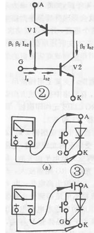
unidirectional thyristor သည် PN junction semiconductor ပစ္စည်းသုံးမျိုးဖြင့် ဖွဲ့စည်းထားပြီး ၎င်း၏ အခြေခံဖွဲ့စည်းပုံ၊ သင်္ကေတနှင့် ညီမျှသော circuit ကို ပုံ 1 တွင် ပြထားသည်။
Thyristor has three electrodes: anode (A), cathode (K) and control electrode (G). From the equivalent circuit point of view, the anode (A) and the control electrode (G) are two PN junctions connected in series with opposite polarities, and the control electrode (G) and the cathode (K) are a PN junction. According to the unidirectional conductivity characteristics of the PN junction, select the appropriate resistance file of the pointer multimeter, and test the positive and negative resistance between the poles (the same two poles, exchange the two resistance values measured by the test pen). For the normal thyristor, G The forward and reverse resistances between G and K are very different; the forward and reverse resistances between G and K and A are very small, and their resistance values are very large. This test result is unique, and the polarity of the thyristor can be determined based on this uniqueness. Use a multimeter to measure the forward and reverse resistances between the SCR electrodes in the R×1K file, and select the two electrodes with a large difference in forward and reverse resistance. For the control electrode (G), the red test lead is connected to the cathode (K), and the remaining electrode is the anode (A). By judging the polarity of the thyristor, the quality of the thyristor can also be determined qualitatively. If the difference between the forward and reverse resistances of any two poles in the test is very small, and the resistance values are very large, it indicates that there is an open-circuit fault between G and K; if the forward and reverse resistances between the two poles are very small and approaching At zero, there is an inter-electrode short-circuit fault inside the SCR.
တစ်လမ်းသွား SCR အစပျိုးလက္ခဏာစမ်းသပ်မှု-
The one-way thyristor is the same in that both have unidirectional conductivity, but the difference is that the conduction of the thyristor is also controlled by the voltage of the gate. ဆိုလိုသည်မှာ thyristor ကိုဖွင့်ရန်အတွက် အခြေအနေနှစ်ခုကို ဖြည့်ဆည်းပေးရမည်- anode (A) နှင့် cathode (K) အကြား အပြုသဘောဆောင်သော ဗို့အားကို အသုံးချသင့်ပြီး ထိန်းချုပ်လျှပ်ကူးပစ္စည်းကြားတွင် ရှေ့ဗို့အားကိုလည်း အသုံးချသင့်သည် ( G) နှင့် cathode (K)။ Thyristor ကိုဖွင့်သောအခါ၊ ထိန်းချုပ်လျှပ်ကူးပစ္စည်းသည် ၎င်း၏လုပ်ဆောင်မှု ဆုံးရှုံးသွားပါသည်။ unidirectional thyristor ၏ conduction process ကို ပုံ 2 တွင်ပြထားသည့် ညီမျှသော circuit ဖြင့် သရုပ်ဖော်နိုင်သည်- PNP tube ၏ emitter သည် thyristor (A) ၏ anode နှင့် ညီမျှပြီး NPN tube ၏ emitter သည် cathode နှင့် ညီမျှသည်။ thyristor (K) ၊ PNP tube ၏ စုဆောင်းသူသည် thyristor ၏ control electrode (G) နှင့် ညီမျှသော NPN tube ၏ အခြေခံနှင့် ချိတ်ဆက်ထားသည်။ A နှင့် K အကြား ခွင့်ပြုနိုင်သော ရှေ့ဗို့အား သက်ရောက်သောအခါ၊ ပြွန်နှစ်ခုသည် လည်ပတ်နေမည်မဟုတ်ပါ။ At this time, when the forward voltage is applied between G and K, the base of the control current flowing into V2 is formed, and so on. ပြွန်နှစ်ခုကို အပြည့်အဝချိတ်ဆက်သည်အထိ။ ဖွင့်သည့်အခါ၊ Ig=O ဆိုလျှင်ပင်၊ V2 တွင် အခြေခံလျှပ်စီးကြောင်းရှိပြီး Ig ထက် များစွာကြီးမားသောကြောင့်၊ ပြွန်နှစ်ခုကို ဖွင့်ထားဆဲဖြစ်သည်။ conductive thyristor ကို ဖြတ်တောက်ရန်၊ ရှေ့သို့ A နှင့် K ၏ ဗို့အားကို သတ်မှတ်ထားသော တန်ဖိုးတစ်ခုသို့ လျှော့ချရမည် သို့မဟုတ် ပြောင်းပြန်၊ သို့မဟုတ် ချိတ်ဆက်မှု ဖြတ်တောက်ရပါမည်။ According to the conductive characteristics of the SCR, the resistance file of a multimeter can be used for testing. For low-power thyristor, connect the circuit as shown in Figure 3(a), connect a touch switch between thyristor A and G (for ease of operation), use the R×1Ω gear of the multimeter, and connect the black test lead. A pole, the red test lead is connected to K. ဤအချိန်တွင်၊ အပြုသဘောဆောင်သောဗို့အားကို thyristor (မာလ်တီမီတာတွင် ချိတ်ထားသည့် ခြောက်သွေ့သောဘက်ထရီမှတဆင့်) သက်ရောက်သည်။ The pointer of the multimeter does not move and the thyristor does not conduct. ခလုတ်ကို နှိပ်သောအခါ A, G သည် G နှင့် K အကြားတွင် trigger voltage ကိုအသုံးပြုသောအခါ၊ thyristor ကိုဖွင့်ထားပြီး multimeter ၏ညွှန်ပြချက်သည် သေးငယ်သောတန်ဖိုးသို့ညွှန်ပြသည်။ G နှင့် A အဆက်ပြတ်သွားသောအခါ ထိန်းချုပ်မှုဗို့အား ဆုံးရှုံးသွားပါသည်။ အကယ်၍ multimeter ၏ညွှန်ပြချက်သည် အနေအထားမပြောင်းလဲပါက၊ thyristor သည် conducting အခြေအနေတွင်ရှိနေဆဲဖြစ်ပြီး thyristor ၏ အစပျိုးခြင်းလက္ခဏာများသည် ကောင်းမွန်ကြောင်း ညွှန်ပြသည်။ G နှင့် A သည် အဆက်ပြတ်နေပါက၊ multimeter ၏ pointer သည် ကွဲထွက်ပြီး ∞ သို့ ညွှန်ပြမည်ဖြစ်သည်။ ဆိုလိုသည်မှာ၊ သိုင်းရစ်စတာသည် လည်ပတ်နေခြင်းမရှိပါက၊ ၎င်းသည် thyristor ၏အစပျိုးခြင်းလက္ခဏာမကောင်း သို့မဟုတ် ပျက်စီးသွားကြောင်း ညွှန်ပြသည်။ ပါဝါမြင့်မားသော thyristors များအတွက်၊ ကြီးမားသော turn-on ဗို့အားကျဆင်းမှုကြောင့်၊ ပြုပြင်ထိန်းသိမ်းမှုလျှပ်စီးအား ထိန်းသိမ်းရန်ခက်ခဲပြီး conduction state ကို ညံ့စေသည်။ ဤအချိန်တွင်၊ ပုံတွင်ပြထားသည့်အတိုင်း thyristor ၏ anode (A) နှင့် ခြောက်သွေ့သောဘက်ထရီကို ဆက်တိုက်ချိတ်ဆက်သင့်သည်။ အမှားအယွင်းမရှိစေရန် 3(b) တွင်ပြထားသည့် circuit ကို စမ်းသပ်သင့်သည်။ ပါဝါမြင့်သော thyristor အတွက်၊ စမ်းသပ်မှုအကျိုးသက်ရောက်မှုကို သိသာထင်ရှားစေရန် ပုံ 3(b) ၏ circuit တွင် အခြောက်ခံဆဲလ်တစ်ခုကို ချိတ်ဆက်သင့်သည်။ ယေဘူယျအားဖြင့်၊ 10A အောက်တစ်ကြောင်း SCR များကို စမ်းသပ်သောအခါ၊ ပုံ 3(a) တွင်ပြသထားသည့် ချိတ်ဆက်ပတ်လမ်းကို အသုံးပြုပါ။ 10A-100A SCR များအတွက်၊ 3A အထက်တွင် ထိန်းချုပ်နိုင်သော တစ်လမ်းမောင်းကို စမ်းသပ်ရန် ပုံ 100(b) တွင် ပြထားသည့် ချိတ်ဆက်ပတ်လမ်းကို အသုံးပြုပါ။
one-way thyristors ကို စမ်းသပ်ခြင်း၏ အခြေခံပေါ်တွင်၊ အခြားသော thyristors အမျိုးအစားများကိုလည်း ၎င်းတို့၏ အခြေခံတည်ဆောက်ပုံအရ multimeter ဖြင့် စမ်းသပ်နိုင်သည်။