
- 27
- Oct
SCRを検出する方法は?
SCRを検出する方法は?
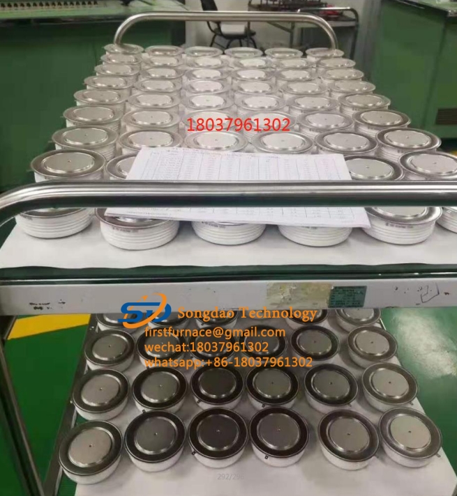
サイリスタ is the abbreviation for silicon controlled rectifier. There are several types of SCRs: one-way, two-way, turn-off and light-controlled. It has the advantages of small size, light weight, high efficiency, long life, convenient control, etc. It is widely used in various automatic control and high-power electric energy conversion occasions such as controllable rectification, voltage regulation, inverter, and non-contact switch. .
SCRの導通条件:XNUMXつは、サイリスタのアノードとカソードの間に順方向電圧を印加する必要があること、もうXNUMXつは、制御電極に順方向電圧を印加する必要があることです。 上記のXNUMXつの条件を同時に満たす必要があり、サイリスタは導通状態になります。 また、サイリスタをONすると、ゲート電圧を下げたり、ゲート電圧を外したりしても、サイリスタはONのままです。 SCRターンオフ条件:SCRアノードとカソードの間の順方向電圧を低減または除去して、アノード電流が最小保守電流よりも小さくなるようにします。
1.サイリストの特性:
サイリスタは一方向サイリスタと双方向サイリスタに分けられます。
一方向サイリスタには、アノードA、カソードK、および制御電極GのXNUMXつのリードピンがあります。
トライアックは、第1のアノードA1(T1)、第2のアノードA2(T2)、および制御電極Gの3つのリードピンを有する。
一方向SCRアノードAとカソードKの間に正の電圧が印加され、必要な順方向トリガー電圧が制御電極Gとカソードの間に印加された場合にのみ、導通するようにトリガーできます。 このとき、AとKの間は低抵抗の導通状態にあり、アノードAとカソードKの間の電圧降下は約1Vです。 一方向SCRがオンになった後、コントローラGがトリガー電圧を失っても、アノードAとカソードKの間に正の電圧が維持されている限り、一方向SCRは低抵抗のままです。伝導状態。 アノードAの電圧が除去されるか、アノードAとカソードKの間の電圧極性が変更された場合(ACゼロ交差)にのみ、一方向サイリスタは低抵抗の導通状態から高抵抗のカットオフ状態に切り替わります。 一方向サイリスタが遮断されると、アノードAとカソードKの間に正の電圧が再印加された場合でも、制御電極GとカソードKの間に正のトリガー電圧を再印加してオンにする必要があります。 一方向SCRのオンとオフの状態は、スイッチのオンとオフの状態と同等であり、非接触スイッチを作成するために使用できます。
双方向サイリスタの第1のアノードA1と第2のアノードA2との間で、印加電圧の極性が順方向であるか逆方向であるかに関係なく、異なる正極性および負極性のトリガー電圧が制御電極Gと第1のアノードとの間に印加される限り。 A1、それは可能性がありますトリガー伝導は低インピーダンス状態にあります。 このとき、A2とA1間の電圧降下も約1Vです。 トライアックがオンになると、トリガー電圧が失われた場合でも、トライアックは引き続きオンになります。 第2アノードA1と第1アノードA2の電流が減少してメンテナンス電流よりも少ない場合、またはA1とA2の間の電圧極性が変化し、トリガー電圧がない場合にのみ、トライアックは遮断されます。 現時点では、トリガー電圧は再印加のみ可能です。 伝導。
2.一方向SCRの検出:
マルチメータは抵抗R *1Ωを選択し、赤と黒のテストリードを使用して、読み取り値が数十オームのピンのペアが見つかるまで、任意の10つのピン間の順方向および逆方向の抵抗を測定します。 このとき、黒のテストリードのピンは制御電極G、赤のテストリードのピンはカソードK、もう一方のフリーピンはアノードAです。このとき、黒のテストリードをアノードAを判断し、赤いテストリードをカソードKに導きます。この時点では、マルチメーターのポインターは動かないはずです。 短いワイヤーを使用して、アノードAと制御電極Gを瞬時に接続します。このとき、マルチメーター電気ブロッキングポインターは右に偏向する必要があり、抵抗の読み取り値は約XNUMXオームです。 アノードAが黒いテストリードに接続され、カソードKが赤いテストリードに接続されている場合、マルチメータのポインタがたわみ、一方向SCRが故障して損傷していることを示します。
3.トライアック検出:
Use the multimeter resistance R*1Ω block, use the red and black meter pens to measure the positive and negative resistance between any two pins, and the results of the two sets of readings are infinite. If one set is tens of ohms, the two pins connected to the set of red and black watches are the first anode A1 and the control electrode G, and the other free pin is the second anode A2. After determining the A1 and G poles, carefully measure the positive and reverse resistances between the A1 and G poles. The pin connected to the black test lead with the relatively small reading is the first anode A1, and the pin connected to the red test lead is Control pole G. Connect the black test lead to the determined second anode A2 and the red test lead to the first anode A1. At this time, the pointer of the multimeter should not be deflected, and the resistance value is infinite. Then use a short wire to short the A2 and G poles instantaneously, and apply a positive trigger voltage to the G pole. The resistance between A2 and A1 is about 10 ohms. Then disconnect the short wire between A2 and G, and the multimeter reading should keep about 10 ohms. Interchange the red and black test leads, connect the red test lead to the second anode A2, and the black test lead to the first anode A1. Similarly, the pointer of the multimeter should not be deflected, and the resistance should be infinite. Use a short wire to short-circuit the A2 and G poles again instantly, and apply a negative trigger voltage to the G pole. The resistance between A1 and A2 is also about 10 ohms. Then disconnect the short wire between the A2 and G poles, and the multimeter reading should remain unchanged at about 10 ohms. In accordance with the above rules, it indicates that the tested triac is not damaged and the polarity of the three pins is judged correctly.
高出力SCRを検出する場合、トリガー電圧を上げるために、1.5V乾電池をマルチメーターの黒いペンと直列に接続する必要があります。
4.サイリスタ(SCR)のピン識別:
サイリスタピンの判定は、以下の方法で行うことができます。まず、マルチメータR * 1Kで10つのピン間の抵抗を測定します。 抵抗が小さいXNUMXつのピンは制御電極とカソードで、残りのピンはアノードです。 次に、マルチメータをR * XNUMXKブロックに入れ、アノードともう一方の脚を指でつまみ、両足を触れさせないで、黒いテストリードをアノードに接続し、赤いテストリードを残りの脚に接続します。 針が右に振れる場合は、陰極として接続されている赤いテストリードを意味します。針が振れない場合は、制御電極です。
一方向サイリスタは1つのPN接合半導体材料で構成されており、その基本構造、記号、等価回路を図XNUMXに示します。
Thyristor has three electrodes: anode (A), cathode (K) and control electrode (G). From the equivalent circuit point of view, the anode (A) and the control electrode (G) are two PN junctions connected in series with opposite polarities, and the control electrode (G) and the cathode (K) are a PN junction. According to the unidirectional conductivity characteristics of the PN junction, select the appropriate resistance file of the pointer multimeter, and test the positive and negative resistance between the poles (the same two poles, exchange the two resistance values measured by the test pen). For the normal thyristor, G The forward and reverse resistances between G and K are very different; the forward and reverse resistances between G and K and A are very small, and their resistance values are very large. This test result is unique, and the polarity of the thyristor can be determined based on this uniqueness. Use a multimeter to measure the forward and reverse resistances between the SCR electrodes in the R×1K file, and select the two electrodes with a large difference in forward and reverse resistance. For the control electrode (G), the red test lead is connected to the cathode (K), and the remaining electrode is the anode (A). By judging the polarity of the thyristor, the quality of the thyristor can also be determined qualitatively. If the difference between the forward and reverse resistances of any two poles in the test is very small, and the resistance values are very large, it indicates that there is an open-circuit fault between G and K; if the forward and reverse resistances between the two poles are very small and approaching At zero, there is an inter-electrode short-circuit fault inside the SCR.
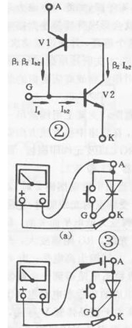
一方向SCRトリガー特性テスト:
The one-way thyristor is the same in that both have unidirectional conductivity, but the difference is that the conduction of the thyristor is also controlled by the voltage of the gate. つまり、サイリスタをオンにするには、XNUMXつの条件が満たされている必要があります。アノード(A)とカソード(K)の間に正の電圧を印加し、制御電極( G)およびカソード(K)。 サイリスタがオンになると、制御電極はその機能を失います。 一方向サイリスタの導通プロセスは、図2に示す等価回路で説明できます。PNPチューブのエミッタはサイリスタのアノード(A)に相当し、NPNチューブのエミッタはのカソードに相当します。サイリスタ(K)、PNP管のコレクタは、サイリスタの制御電極(G)に相当するNPN管のベースに接続されています。 許容順方向電圧がAとKの間に印加されると、XNUMXつのチューブは導通しません。 At this time, when the forward voltage is applied between G and K, the base of the control current flowing into V2 is formed, and so on. XNUMX本のチューブが完全に接続されるまで。 オンにすると、Ig = Oの場合でも、V2にはベース電流があり、Igよりもはるかに大きいため、XNUMXつのチューブはオンのままです。 導電性サイリスタを遮断するには、AとKの順方向電圧を特定の値に下げるか、逆にするか、切断する必要があります。 According to the conductive characteristics of the SCR, the resistance file of a multimeter can be used for testing. For low-power thyristor, connect the circuit as shown in Figure 3(a), connect a touch switch between thyristor A and G (for ease of operation), use the R×1Ω gear of the multimeter, and connect the black test lead. A pole, the red test lead is connected to K. このとき、サイリスタには(マルチメータに取り付けられた乾電池を介して)正の電圧が印加されます。 The pointer of the multimeter does not move and the thyristor does not conduct. スイッチを押すと、A、Gトリガー電圧がGとKの間に印加されると、サイリスタがオンになり、マルチメータのポインタがたわみ、小さい値を指します。 GとAが切断されると、制御電圧が失われます。 マルチメータのポインタの場合位置が変わらない場合、サイリスタは導通状態のままであり、サイリスタのトリガ特性が良好であることを示しています。 GとAが切断されている場合、マルチメータのポインタは偏向し、∞を指します。 つまり、サイリスタが導通していない場合は、サイリスタのトリガ特性が良くないか、損傷していることを示しています。 高出力のサイリスタでは、ターンオン電圧降下が大きいため、維持電流の維持が難しく、導通状態が悪くなります。 このとき、図に示すように、乾電池をサイリスタのアノード(A)に直列に接続する必要があります。 3(b)に示す回路は、誤判定を避けるためにテストする必要があります。 高出力サイリスタの場合、テスト効果を明確にするために、図3(b)の回路に乾電池を直列に接続する必要があります。 一般的に、10A未満の一方向SCRをテストする場合は、図3(a)に示す接続回路を使用します。 10A-100A SCRの場合、図3(b)に示す接続回路を使用して、100Aを超える一方向制御可能をテストします。
一方向サイリスタのテストに基づいて、他のタイプのサイリスタも基本構造に従ってマルチメータでテストできます。