
- 27
- Oct
Kako otkriti SCR?
Kako otkriti SCR?
tiristor is the abbreviation for silicon controlled rectifier. There are several types of SCRs: one-way, two-way, turn-off and light-controlled. It has the advantages of small size, light weight, high efficiency, long life, convenient control, etc. It is widely used in various automatic control and high-power electric energy conversion occasions such as controllable rectification, voltage regulation, inverter, and non-contact switch. .
SCR conduction conditions: one is that a forward voltage must be applied between the anode and cathode of the thyristor, and the other is that a forward voltage must be applied to the control electrode. The above two conditions must be met at the same time, the thyristor will be in the conducting state. In addition, once the thyristor is turned on, even if the gate voltage is reduced or the gate voltage is removed, the thyristor is still turned on. SCR turn-off conditions: reduce or remove the forward voltage between the SCR anode and the cathode, so that the anode current is less than the minimum maintenance current.
1. Karakteristike tiristora:
Tiristor se dijeli na jednosmjerni tiristor i dvosmjerni tiristor.
Jednosmjerni tiristor ima tri olovne igle: anodu A, katodu K i kontrolnu elektrodu G.
The triac has a first anode A1 (T1), a second anode A2 (T2), and a control electrode G three lead pins.
Samo kada se između jednosmjerne SCR anode A i katode K primijeni pozitivan napon, a između kontrolne elektrode G i katode, može se pokrenuti zahtijevani prednji okidač napon. U ovom trenutku između A i K postoji vodljivo stanje niskog otpora, a pad napona između anode A i katode K je oko 1V. Nakon što je jednosmjerni SCR uključen, čak i ako regulator G izgubi napon okidača, sve dok se održava pozitivan napon između anode A i katode K, jednosmjerni SCR nastavlja biti u niskom otporu stanje provođenja. Tek kada se ukloni napon anode A ili se promijeni polaritet napona između anode A i katode K (prijelaz AC nule), jednosmjerni tiristor će se prebaciti iz vodljivog stanja niskog otpora u stanje prekida s visokim otporom. Nakon što je jednosmjerni tiristor prekinut, čak i ako se pozitivni napon ponovno primijeni između anode A i katode K, mora se ponovno primijeniti pozitivni napon okidača između kontrolne elektrode G i katode K koja se uključuje. Uključeno i isključeno stanje jednosmjernog SCR-a ekvivalentno je stanju uključivanja i isključivanja prekidača i može se koristiti za izradu beskontaktne sklopke.
Between the first anode A1 and the second anode A2 of the bidirectional thyristor, regardless of whether the applied voltage polarity is forward or reverse, as long as the trigger voltage with different positive and negative polarity is applied between the control electrode G and the first anode A1, it can be The trigger conduction is in a low-impedance state. At this time, the voltage drop between A1 and A2 is also about 1V. Once the triac is turned on, it can continue to be turned on even if the trigger voltage is lost. Only when the current of the first anode A1 and the second anode A2 decreases and is less than the maintenance current or when the voltage polarity between A1 and A2 changes and there is no trigger voltage, the triac will be cut off. At this time, the trigger voltage can only be reapplied. Conduction.
2. Otkrivanje jednosmjernog SCR-a:
Multimetar odabire otpor R*1Ω, a crveni i crni ispitni vodovi koriste se za mjerenje otpora naprijed i nazad između bilo koje dvije igle dok se ne pronađe par iglica s očitanjem od desetke oma. U ovom trenutku, igla crnog ispitnog vodiča je kontrolna elektroda G , igla crvenog ispitnog kabela je katoda K, a drugi slobodni iglica je anoda A. U ovom trenutku, spojite crni ispitni kabel na procijenjena anoda A, a crveni ispitni kabel do katode K. Pokazivač multimetra se u ovom trenutku ne bi trebao pomicati. Upotrijebite kratku žicu za trenutačno povezivanje anode A i kontrolne elektrode G. U ovom trenutku, pokazivač električnog blokiranja multimetra trebao bi biti skrenut udesno, a očitanje otpora je oko 10 ohma. Ako je anoda A spojena na crni ispitni kabel, a katoda K spojena na crveni ispitni kabel, pokazivač multimetra će se skrenuti, što pokazuje da je jednosmjerni SCR pokvaren i oštećen.
3. Otkrivanje trijaka:
Use the multimeter resistance R*1Ω block, use the red and black meter pens to measure the positive and negative resistance between any two pins, and the results of the two sets of readings are infinite. If one set is tens of ohms, the two pins connected to the set of red and black watches are the first anode A1 and the control electrode G, and the other free pin is the second anode A2. After determining the A1 and G poles, carefully measure the positive and reverse resistances between the A1 and G poles. The pin connected to the black test lead with the relatively small reading is the first anode A1, and the pin connected to the red test lead is Control pole G. Connect the black test lead to the determined second anode A2 and the red test lead to the first anode A1. At this time, the pointer of the multimeter should not be deflected, and the resistance value is infinite. Then use a short wire to short the A2 and G poles instantaneously, and apply a positive trigger voltage to the G pole. The resistance between A2 and A1 is about 10 ohms. Then disconnect the short wire between A2 and G, and the multimeter reading should keep about 10 ohms. Interchange the red and black test leads, connect the red test lead to the second anode A2, and the black test lead to the first anode A1. Similarly, the pointer of the multimeter should not be deflected, and the resistance should be infinite. Use a short wire to short-circuit the A2 and G poles again instantly, and apply a negative trigger voltage to the G pole. The resistance between A1 and A2 is also about 10 ohms. Then disconnect the short wire between the A2 and G poles, and the multimeter reading should remain unchanged at about 10 ohms. In accordance with the above rules, it indicates that the tested triac is not damaged and the polarity of the three pins is judged correctly.
Prilikom otkrivanja SCR-a velike snage, suhu bateriju od 1.5 V potrebno je spojiti u seriju s crnom olovkom multimetra kako bi se povećao napon okidača.
4. Identifikacija pinova tiristora (SCR):
Procjena pinova tiristora može se izvršiti na sljedeće načine: Najprije multimetrom R*1K izmjerite otpor između tri pina. Dva igla s manjim otporom su kontrolna elektroda i katoda, a preostali pin je anoda. Zatim stavite multimetar u blok R*10K, prstima stisnite anodu i drugu nogu i ne dopustite da se dvije noge dodiruju, spojite crni ispitni kabel na anodu, a crveni ispitni kabel na preostalu nogu. Ako se igla zamahne udesno, to znači da je crveni ispitni kabel spojen kao katoda, ako se ne zamahne, to je kontrolna elektroda.
The unidirectional thyristor is composed of three PN junction semiconductor materials, and its basic structure, symbol and equivalent circuit are shown in Figure 1.
Thyristor has three electrodes: anode (A), cathode (K) and control electrode (G). From the equivalent circuit point of view, the anode (A) and the control electrode (G) are two PN junctions connected in series with opposite polarities, and the control electrode (G) and the cathode (K) are a PN junction. According to the unidirectional conductivity characteristics of the PN junction, select the appropriate resistance file of the pointer multimeter, and test the positive and negative resistance between the poles (the same two poles, exchange the two resistance values measured by the test pen). For the normal thyristor, G The forward and reverse resistances between G and K are very different; the forward and reverse resistances between G and K and A are very small, and their resistance values are very large. This test result is unique, and the polarity of the thyristor can be determined based on this uniqueness. Use a multimeter to measure the forward and reverse resistances between the SCR electrodes in the R×1K file, and select the two electrodes with a large difference in forward and reverse resistance. For the control electrode (G), the red test lead is connected to the cathode (K), and the remaining electrode is the anode (A). By judging the polarity of the thyristor, the quality of the thyristor can also be determined qualitatively. If the difference between the forward and reverse resistances of any two poles in the test is very small, and the resistance values are very large, it indicates that there is an open-circuit fault between G and K; if the forward and reverse resistances between the two poles are very small and approaching At zero, there is an inter-electrode short-circuit fault inside the SCR.

Test karakteristike jednosmjernog SCR okidača:
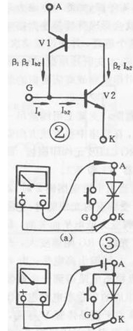
The one-way thyristor is the same in that both have unidirectional conductivity, but the difference is that the conduction of the thyristor is also controlled by the voltage of the gate. That is to say, two conditions must be met for the thyristor to be turned on: a positive voltage should be applied between the anode (A) and the cathode (K), and a forward voltage should also be applied between the control electrode (G) and the cathode (K) . Kada se tiristor uključi, upravljačka elektroda gubi svoju funkciju. Proces vođenja jednosmjernog tiristora može se ilustrirati ekvivalentnim krugom prikazanim na slici 2: emiter PNP cijevi je ekvivalentan anodi tiristora (A), a emiter NPN cijevi je ekvivalent katodi tiristor (K) , Kolektor PNP cijevi spojen je na bazu NPN cijevi, što je ekvivalentno kontrolnoj elektrodi (G) tiristora. Kada se dopušteni prednji napon primjenjuje između A i K, dvije cijevi neće voditi. At this time, when the forward voltage is applied between G and K, the base of the control current flowing into V2 is formed, and so on. Until the two tubes are fully connected. Kada je uključen, čak i ako je Ig=O, jer V2 ima osnovnu struju i mnogo je veći od Ig, dvije cijevi su i dalje uključene. Da bi se vodljivi tiristor prekinuo, prednji napon A i K mora se smanjiti na određenu vrijednost, ili obrnuti, ili isključiti. According to the conductive characteristics of the SCR, the resistance file of a multimeter can be used for testing. For low-power thyristor, connect the circuit as shown in Figure 3(a), connect a touch switch between thyristor A and G (for ease of operation), use the R×1Ω gear of the multimeter, and connect the black test lead. A pole, the red test lead is connected to K. U ovom trenutku na tiristor se primjenjuje pozitivan napon (kroz suhu bateriju pričvršćenu na multimetar). The pointer of the multimeter does not move and the thyristor does not conduct. When the switch is pressed, A, G When the trigger voltage is applied between G and K, the thyristor is turned on, and the pointer of the multimeter deflects and points to a smaller value; when G and A are disconnected, the control voltage is lost. If the pointer of the multimeter If the position remains unchanged, the thyristor is still in the conducting state, indicating that the triggering characteristics of the thyristor are good. If G and A are disconnected, the pointer of the multimeter will be deflected and point to ∞. That is, if the thyristor is not conducting, it indicates that the triggering characteristic of the thyristor is not good or has been damaged. Za tiristore veće snage, zbog velikog pada napona uključivanja, struju održavanja je teško održavati, zbog čega je stanje vodljivosti loše. At this time, a dry battery should be connected in series to the anode (A) of the thyristor, as shown in the figure. Krug prikazan u 3(b) treba ispitati kako bi se izbjegla pogrešna procjena. For high-power thyristor, a dry cell should be connected in series on the circuit of Figure 3(b) to make the test effect obvious. Općenito govoreći, kada testirate jednosmjerne SCR-ove ispod 10A, koristite spojni krug prikazan na slici 3(a); za 10A-100A SCR-ove, upotrijebite spojni krug prikazan na slici 3(b) kako biste testirali jednosmjerno upravljivo iznad 100A.
Na temelju ispitivanja jednosmjernih tiristora, multimetrom se mogu ispitati i druge vrste tiristora prema njihovoj osnovnoj strukturi.