
- 27
- Oct
Hogyan lehet felismerni az SCR-t?
Hogyan lehet felismerni az SCR-t?
Tirisztor is the abbreviation for silicon controlled rectifier. There are several types of SCRs: one-way, two-way, turn-off and light-controlled. It has the advantages of small size, light weight, high efficiency, long life, convenient control, etc. It is widely used in various automatic control and high-power electric energy conversion occasions such as controllable rectification, voltage regulation, inverter, and non-contact switch. .
SCR conduction conditions: one is that a forward voltage must be applied between the anode and cathode of the thyristor, and the other is that a forward voltage must be applied to the control electrode. The above two conditions must be met at the same time, the thyristor will be in the conducting state. In addition, once the thyristor is turned on, even if the gate voltage is reduced or the gate voltage is removed, the thyristor is still turned on. SCR turn-off conditions: reduce or remove the forward voltage between the SCR anode and the cathode, so that the anode current is less than the minimum maintenance current.
1. A tirisztor jellemzői:
A tirisztor egyirányú tirisztorra és kétirányú tirisztorra oszlik.
Az egyirányú tirisztornak három vezeték érintkezője van: A anód, K katód és G vezérlőelektród.
A triacnak van egy első A1 anódja (T1), egy második A2 anódja (T2), és egy G vezérlőelektródája három vezetékes érintkezős.
Csak akkor indítható vezetésre, ha pozitív feszültség van az egyirányú SCR anód A és a K katód között, és a szükséges előremenő indítófeszültséget a G vezérlőelektród és a katód között. Ekkor A és K között kis ellenállású vezetési állapot van, és az A anód és a K katód közötti feszültségesés körülbelül 1 V. Az egyirányú SCR bekapcsolása után még akkor is, ha a G vezérlő elveszíti a triggerfeszültséget, mindaddig, amíg a pozitív feszültség megmarad az A anód és a K katód között, az egyirányú SCR továbbra is alacsony ellenállású. vezetési állapot. Csak akkor, ha az A anód feszültségét eltávolítják, vagy az A anód és a K katód közötti feszültség polaritást megváltoztatják (AC nulla keresztezés), az egyirányú tirisztor kis ellenállású vezetési állapotból nagy ellenállású lekapcsolási állapotba vált át. Az egyirányú tirisztor lekapcsolása után még akkor is, ha a pozitív feszültség újra van kapcsolva az A anód és a K katód között, a bekapcsoláshoz ismét pozitív indítófeszültséget kell kapcsolni a G vezérlőelektród és a K katód közé. Az egyirányú SCR be- és kikapcsolt állapota megegyezik a kapcsoló be- és kikapcsolt állapotával, és érintésmentes kapcsoló készíthető belőle.
A kétirányú tirisztor első A1 és második A2 anódja között, függetlenül attól, hogy az alkalmazott feszültség polaritás előre vagy fordított, mindaddig, amíg eltérő pozitív és negatív polaritású triggerfeszültség van a G vezérlőelektród és az első anód között A1, lehet A trigger vezetés alacsony impedanciájú állapotban van. Ekkor az A1 és A2 közötti feszültségesés is körülbelül 1 V. A triac bekapcsolása után továbbra is bekapcsolható még akkor is, ha az indítófeszültség elveszik. A triac csak akkor szakad meg, ha az első A1 anód és a második A2 anód árama csökken, és kisebb, mint a karbantartási áram, vagy ha az A1 és A2 közötti feszültség polaritás megváltozik, és nincs kioldó feszültség. Ekkor az indítófeszültséget csak újra lehet kapcsolni. Vezetés.
2. Egyirányú SCR észlelése:
A multiméter kiválasztja az R*1Ω ellenállást, és a piros és fekete mérőzsinórok segítségével mérik az előremenő és fordított ellenállást bármely két érintkező között, amíg meg nem talál egy pár tíz ohmos leolvasást. Ekkor a fekete mérővezeték tűje a G vezérlőelektróda, a piros mérővezeték tűje a K katód, a másik szabad érintkező pedig az A anód. Ekkor csatlakoztassa a fekete mérővezetéket a az A anódot, a piros tesztet pedig a K katódhoz vezeti. A multiméter mutatója ekkor nem mozoghat. Egy rövid vezeték segítségével azonnal csatlakoztassa az A anódot és a G vezérlőelektródát. Ekkor a multiméter elektromos blokkoló mutatóját jobbra kell fordítani, és az ellenállás értéke körülbelül 10 ohm. Ha az A anód a fekete mérővezetékhez, a K katód pedig a piros mérővezetékhez csatlakozik, a multiméter mutatója elhajlik, jelezve, hogy az egyirányú SCR meghibásodott és megsérült.
3. Triák észlelése:
Use the multimeter resistance R*1Ω block, use the red and black meter pens to measure the positive and negative resistance between any two pins, and the results of the two sets of readings are infinite. If one set is tens of ohms, the two pins connected to the set of red and black watches are the first anode A1 and the control electrode G, and the other free pin is the second anode A2. After determining the A1 and G poles, carefully measure the positive and reverse resistances between the A1 and G poles. The pin connected to the black test lead with the relatively small reading is the first anode A1, and the pin connected to the red test lead is Control pole G. Connect the black test lead to the determined second anode A2 and the red test lead to the first anode A1. At this time, the pointer of the multimeter should not be deflected, and the resistance value is infinite. Then use a short wire to short the A2 and G poles instantaneously, and apply a positive trigger voltage to the G pole. The resistance between A2 and A1 is about 10 ohms. Then disconnect the short wire between A2 and G, and the multimeter reading should keep about 10 ohms. Interchange the red and black test leads, connect the red test lead to the second anode A2, and the black test lead to the first anode A1. Similarly, the pointer of the multimeter should not be deflected, and the resistance should be infinite. Use a short wire to short-circuit the A2 and G poles again instantly, and apply a negative trigger voltage to the G pole. The resistance between A1 and A2 is also about 10 ohms. Then disconnect the short wire between the A2 and G poles, and the multimeter reading should remain unchanged at about 10 ohms. In accordance with the above rules, it indicates that the tested triac is not damaged and the polarity of the three pins is judged correctly.
A nagy teljesítményű SCR-ek észlelésekor egy 1.5 V-os szárazelemet sorba kell kötni a multiméter fekete tollával, hogy növelje a triggerfeszültséget.
4. A tirisztor tűs azonosítója (SCR):
A tirisztor tűinek megítélése a következő módokon történhet: Először is mérje meg a három érintkező közötti ellenállást egy R*1K multiméterrel. A két kisebb ellenállású érintkező a vezérlőelektróda és a katód, a fennmaradó érintkező pedig az anód. Ezután tegye a multimétert az R*10K blokkba, ujjaival csípje meg az anódot és a másik lábát, és ne hagyja, hogy a két láb összeérjen, csatlakoztassa a fekete mérővezetéket az anódhoz, a piros mérővezetéket a maradék lábhoz. Ha a tű jobbra lendül, az a piros mérővezetéket jelenti, katódként csatlakoztatva, ha nem lenge, akkor a vezérlőelektróda.
Az egyirányú tirisztor három PN átmenetű félvezető anyagból áll, alapfelépítését, szimbólumát és egyenértékű áramkörét az 1. ábra mutatja.
Thyristor has three electrodes: anode (A), cathode (K) and control electrode (G). From the equivalent circuit point of view, the anode (A) and the control electrode (G) are two PN junctions connected in series with opposite polarities, and the control electrode (G) and the cathode (K) are a PN junction. According to the unidirectional conductivity characteristics of the PN junction, select the appropriate resistance file of the pointer multimeter, and test the positive and negative resistance between the poles (the same two poles, exchange the two resistance values measured by the test pen). For the normal thyristor, G The forward and reverse resistances between G and K are very different; the forward and reverse resistances between G and K and A are very small, and their resistance values are very large. This test result is unique, and the polarity of the thyristor can be determined based on this uniqueness. Use a multimeter to measure the forward and reverse resistances between the SCR electrodes in the R×1K file, and select the two electrodes with a large difference in forward and reverse resistance. For the control electrode (G), the red test lead is connected to the cathode (K), and the remaining electrode is the anode (A). By judging the polarity of the thyristor, the quality of the thyristor can also be determined qualitatively. If the difference between the forward and reverse resistances of any two poles in the test is very small, and the resistance values are very large, it indicates that there is an open-circuit fault between G and K; if the forward and reverse resistances between the two poles are very small and approaching At zero, there is an inter-electrode short-circuit fault inside the SCR.

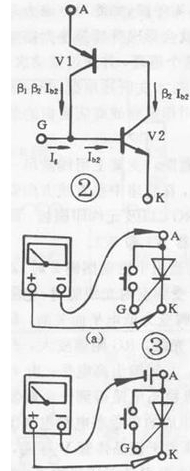
Egyirányú SCR trigger jelleggörbe teszt:
The one-way thyristor is the same in that both have unidirectional conductivity, but the difference is that the conduction of the thyristor is also controlled by the voltage of the gate. That is to say, two conditions must be met for the thyristor to be turned on: a positive voltage should be applied between the anode (A) and the cathode (K), and a forward voltage should also be applied between the control electrode (G) and the cathode (K) . A tirisztor bekapcsolásakor a vezérlőelektróda elveszti funkcióját. Az egyirányú tirisztor vezetési folyamata a 2. ábrán látható ekvivalens áramkörrel szemléltethető: A PNP cső emittere ekvivalens a tirisztor anódjával (A), az NPN cső emittere pedig egyenértékű a tirisztor katódjával. a tirisztor (K) , A PNP cső kollektora az NPN cső aljához csatlakozik, ami egyenértékű a tirisztor vezérlőelektródájával (G). Ha a megengedett előremenő feszültséget A és K közé kapcsoljuk, a két cső nem vezet. At this time, when the forward voltage is applied between G and K, the base of the control current flowing into V2 is formed, and so on. Until the two tubes are fully connected. Bekapcsolva még ha Ig=O is, mert a V2 alapáramú és jóval nagyobb, mint az Ig, a két cső akkor is be van kapcsolva. A vezetőképes tirisztor lekapcsolásához az A és K előremenő feszültségét egy bizonyos értékre kell csökkenteni, vagy megfordítani, vagy le kell választani. According to the conductive characteristics of the SCR, the resistance file of a multimeter can be used for testing. For low-power thyristor, connect the circuit as shown in Figure 3(a), connect a touch switch between thyristor A and G (for ease of operation), use the R×1Ω gear of the multimeter, and connect the black test lead. A pole, the red test lead is connected to K. Ekkor a tirisztorra pozitív feszültség kerül (a multiméterhez csatlakoztatott szárazelemen keresztül). The pointer of the multimeter does not move and the thyristor does not conduct. When the switch is pressed, A, G When the trigger voltage is applied between G and K, the thyristor is turned on, and the pointer of the multimeter deflects and points to a smaller value; when G and A are disconnected, the control voltage is lost. If the pointer of the multimeter If the position remains unchanged, the thyristor is still in the conducting state, indicating that the triggering characteristics of the thyristor are good. Ha G és A nincs összekötve, a multiméter mutatója eltér, és a ∞-ra mutat. Azaz ha a tirisztor nem vezet, az azt jelzi, hogy a tirisztor kioldási karakterisztikája nem jó, vagy megsérült. A nagyobb teljesítményű tirisztoroknál a nagy bekapcsolási feszültségesés miatt a karbantartási áramot nehéz fenntartani, emiatt a vezetési állapot rossz. At this time, a dry battery should be connected in series to the anode (A) of the thyristor, as shown in the figure. A 3(b) pontban bemutatott áramkört meg kell vizsgálni a téves megítélés elkerülése érdekében. Nagy teljesítményű tirisztorok esetén a 3(b) ábra áramkörébe sorba kell kötni egy száraz cellát, hogy a teszt hatás nyilvánvaló legyen. Általánosságban elmondható, hogy a 10 A alatti egyirányú SCR-ek tesztelésekor használja a 3(a) ábrán látható csatlakozó áramkört; 10A-100A SCR-eknél használja a 3(b) ábrán látható csatlakozó áramkört a 100A feletti egyirányú vezérlés teszteléséhez.
Az egyirányú tirisztorok vizsgálata alapján más típusú tirisztorok is vizsgálhatók multiméterrel alapfelépítésüknek megfelelően.