
- 27
- Oct
Bagaimana untuk mengesan SCR?
Bagaimana untuk mengesan SCR?
Thyristor is the abbreviation for silicon controlled rectifier. There are several types of SCRs: one-way, two-way, turn-off and light-controlled. It has the advantages of small size, light weight, high efficiency, long life, convenient control, etc. It is widely used in various automatic control and high-power electric energy conversion occasions such as controllable rectification, voltage regulation, inverter, and non-contact switch. .
SCR conduction conditions: one is that a forward voltage must be applied between the anode and cathode of the thyristor, and the other is that a forward voltage must be applied to the control electrode. The above two conditions must be met at the same time, the thyristor will be in the conducting state. In addition, once the thyristor is turned on, even if the gate voltage is reduced or the gate voltage is removed, the thyristor is still turned on. SCR turn-off conditions: reduce or remove the forward voltage between the SCR anode and the cathode, so that the anode current is less than the minimum maintenance current.
1. The characteristics of thyristor:
The thyristor is divided into one-way thyristor and two-way thyristor.
The unidirectional thyristor has three lead pins: anode A, cathode K, and control electrode G.
The triac has a first anode A1 (T1), a second anode A2 (T2), and a control electrode G three lead pins.
Hanya apabila voltan positif dikenakan antara anod SCR satu arah A dan katod K, dan voltan pencetus ke hadapan yang diperlukan digunakan antara elektrod kawalan G dan katod, bolehkah ia dicetuskan untuk mengalir. Pada masa ini, terdapat keadaan pengaliran rintangan rendah antara A dan K, dan penurunan voltan antara anod A dan katod K adalah kira-kira 1V. Selepas SCR sehala dihidupkan, walaupun pengawal G kehilangan voltan pencetus, selagi voltan positif dikekalkan antara anod A dan katod K, SCR sehala terus berada dalam rintangan rendah keadaan pengaliran. Hanya apabila voltan anod A dialih keluar atau kekutuban voltan antara anod A dan katod K ditukar (persimpangan sifar AC), thyristor satu arah akan bertukar daripada keadaan pengaliran rintangan rendah kepada keadaan pemotongan rintangan tinggi. Sebaik sahaja thyristor satu arah terputus, walaupun voltan positif digunakan semula di antara anod A dan katod K, voltan pencetus positif mesti digunakan semula antara elektrod kawalan G dan katod K untuk dihidupkan. Keadaan hidup dan mati SCR sehala adalah bersamaan dengan keadaan hidup dan mati suis, dan ia boleh digunakan untuk membuat suis bukan hubungan.
Between the first anode A1 and the second anode A2 of the bidirectional thyristor, regardless of whether the applied voltage polarity is forward or reverse, as long as the trigger voltage with different positive and negative polarity is applied between the control electrode G and the first anode A1, it can be The trigger conduction is in a low-impedance state. At this time, the voltage drop between A1 and A2 is also about 1V. Once the triac is turned on, it can continue to be turned on even if the trigger voltage is lost. Only when the current of the first anode A1 and the second anode A2 decreases and is less than the maintenance current or when the voltage polarity between A1 and A2 changes and there is no trigger voltage, the triac will be cut off. At this time, the trigger voltage can only be reapplied. Conduction.
2. Pengesanan SCR sehala:
The multimeter selects the resistance R*1Ω, and the red and black test leads are used to measure the forward and reverse resistance between any two pins until a pair of pins with a reading of tens of ohms is found. At this time, the pin of the black test lead is the control electrode G , The pin of the red test lead is the cathode K, and the other free pin is the anode A. At this time, connect the black test lead to the judged anode A, and the red test lead to the cathode K. The pointer of the multimeter should not move at this time. Use a short wire to instantaneously connect anode A and control electrode G. At this time, the multimeter electric blocking pointer should be deflected to the right, and the resistance reading is about 10 ohms. If the anode A is connected to the black test lead and the cathode K is connected to the red test lead, the pointer of the multimeter will deflect, indicating that the one-way SCR has been broken down and damaged.
3. Pengesanan Triac:
Use the multimeter resistance R*1Ω block, use the red and black meter pens to measure the positive and negative resistance between any two pins, and the results of the two sets of readings are infinite. If one set is tens of ohms, the two pins connected to the set of red and black watches are the first anode A1 and the control electrode G, and the other free pin is the second anode A2. After determining the A1 and G poles, carefully measure the positive and reverse resistances between the A1 and G poles. The pin connected to the black test lead with the relatively small reading is the first anode A1, and the pin connected to the red test lead is Control pole G. Connect the black test lead to the determined second anode A2 and the red test lead to the first anode A1. At this time, the pointer of the multimeter should not be deflected, and the resistance value is infinite. Then use a short wire to short the A2 and G poles instantaneously, and apply a positive trigger voltage to the G pole. The resistance between A2 and A1 is about 10 ohms. Then disconnect the short wire between A2 and G, and the multimeter reading should keep about 10 ohms. Interchange the red and black test leads, connect the red test lead to the second anode A2, and the black test lead to the first anode A1. Similarly, the pointer of the multimeter should not be deflected, and the resistance should be infinite. Use a short wire to short-circuit the A2 and G poles again instantly, and apply a negative trigger voltage to the G pole. The resistance between A1 and A2 is also about 10 ohms. Then disconnect the short wire between the A2 and G poles, and the multimeter reading should remain unchanged at about 10 ohms. In accordance with the above rules, it indicates that the tested triac is not damaged and the polarity of the three pins is judged correctly.
Apabila mengesan SCR berkuasa tinggi, bateri kering 1.5V perlu disambung secara bersiri dengan pen hitam multimeter untuk meningkatkan voltan pencetus.
4. Pengenalan pin thyristor (SCR):
Penghakiman pin thyristor boleh dilakukan dengan cara berikut: Pertama, ukur rintangan antara tiga pin dengan multimeter R*1K. Dua pin dengan rintangan yang lebih kecil ialah elektrod kawalan dan katod, dan pin yang tinggal ialah anod. Kemudian letakkan multimeter di dalam blok R*10K, cubit anod dan kaki yang lain dengan jari anda, dan jangan biarkan kedua-dua kaki bersentuhan, sambungkan plumbum ujian hitam ke anod, dan ujian merah membawa ke kaki yang tinggal. Jika jarum berayun ke kanan, ia bermakna petunjuk ujian merah Disambungkan sebagai katod, jika ia tidak berayun, ia adalah elektrod kawalan.
The unidirectional thyristor is composed of three PN junction semiconductor materials, and its basic structure, symbol and equivalent circuit are shown in Figure 1.
Thyristor has three electrodes: anode (A), cathode (K) and control electrode (G). From the equivalent circuit point of view, the anode (A) and the control electrode (G) are two PN junctions connected in series with opposite polarities, and the control electrode (G) and the cathode (K) are a PN junction. According to the unidirectional conductivity characteristics of the PN junction, select the appropriate resistance file of the pointer multimeter, and test the positive and negative resistance between the poles (the same two poles, exchange the two resistance values measured by the test pen). For the normal thyristor, G The forward and reverse resistances between G and K are very different; the forward and reverse resistances between G and K and A are very small, and their resistance values are very large. This test result is unique, and the polarity of the thyristor can be determined based on this uniqueness. Use a multimeter to measure the forward and reverse resistances between the SCR electrodes in the R×1K file, and select the two electrodes with a large difference in forward and reverse resistance. For the control electrode (G), the red test lead is connected to the cathode (K), and the remaining electrode is the anode (A). By judging the polarity of the thyristor, the quality of the thyristor can also be determined qualitatively. If the difference between the forward and reverse resistances of any two poles in the test is very small, and the resistance values are very large, it indicates that there is an open-circuit fault between G and K; if the forward and reverse resistances between the two poles are very small and approaching At zero, there is an inter-electrode short-circuit fault inside the SCR.

Ujian ciri pencetus SCR sehala:
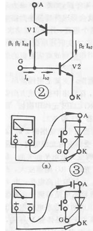
The one-way thyristor is the same in that both have unidirectional conductivity, but the difference is that the conduction of the thyristor is also controlled by the voltage of the gate. That is to say, two conditions must be met for the thyristor to be turned on: a positive voltage should be applied between the anode (A) and the cathode (K), and a forward voltage should also be applied between the control electrode (G) and the cathode (K) . Apabila thyristor dihidupkan, elektrod kawalan kehilangan fungsinya. Proses pengaliran thyristor satu arah boleh digambarkan oleh litar setara yang ditunjukkan dalam Rajah 2: Pemancar tiub PNP adalah bersamaan dengan anod thyristor (A), dan pemancar tiub NPN adalah bersamaan dengan katod thyristor (K) , Pengumpul tiub PNP disambungkan ke pangkal tiub NPN, yang bersamaan dengan elektrod kawalan (G) thyristor. Apabila voltan hadapan yang dibenarkan digunakan antara A dan K, kedua-dua tiub tidak akan mengalir. At this time, when the forward voltage is applied between G and K, the base of the control current flowing into V2 is formed, and so on. Until the two tubes are fully connected. Apabila dihidupkan, walaupun Ig=O, kerana V2 mempunyai arus tapak dan jauh lebih besar daripada Ig, kedua-dua tiub masih dihidupkan. To make the conductive thyristor cut off, the forward voltage of A and K must be reduced to a certain value, or reversed, or disconnected. According to the conductive characteristics of the SCR, the resistance file of a multimeter can be used for testing. For low-power thyristor, connect the circuit as shown in Figure 3(a), connect a touch switch between thyristor A and G (for ease of operation), use the R×1Ω gear of the multimeter, and connect the black test lead. A pole, the red test lead is connected to K. Pada masa ini, voltan positif digunakan pada thyristor (melalui bateri kering yang dipasang pada multimeter). The pointer of the multimeter does not move and the thyristor does not conduct. When the switch is pressed, A, G When the trigger voltage is applied between G and K, the thyristor is turned on, and the pointer of the multimeter deflects and points to a smaller value; when G and A are disconnected, the control voltage is lost. If the pointer of the multimeter If the position remains unchanged, the thyristor is still in the conducting state, indicating that the triggering characteristics of the thyristor are good. If G and A are disconnected, the pointer of the multimeter will be deflected and point to ∞. That is, if the thyristor is not conducting, it indicates that the triggering characteristic of the thyristor is not good or has been damaged. For thyristors with higher power, due to the large turn-on voltage drop, the maintenance current is difficult to maintain, causing the conduction state to be poor. At this time, a dry battery should be connected in series to the anode (A) of the thyristor, as shown in the figure. Litar yang ditunjukkan dalam 3(b) hendaklah diuji untuk mengelakkan salah menilai. For high-power thyristor, a dry cell should be connected in series on the circuit of Figure 3(b) to make the test effect obvious. Secara umumnya, apabila menguji SCR sehala di bawah 10A, gunakan litar sambungan yang ditunjukkan dalam Rajah 3(a); untuk SCR 10A-100A, gunakan litar sambungan yang ditunjukkan dalam Rajah 3(b) untuk menguji kawalan sehala di atas 100A.
On the basis of testing one-way thyristors, other types of thyristors can also be tested with a multimeter according to their basic structure.