- 05
- Aug
Improvement Direction of Induction Heating Pit Annealing Furnace
Improvement Direction of Induction Heating Pit Annealing Furnace
Ka nts’etsopele ea matla a ho futhumatsa supply technology and the progress of induction furnace manufacturing technology, induction heating pit furnaces should be improved to make them a new type of heat treatment furnace that replaces resistance heating pit furnaces and bell furnaces. Specific improvements include the following aspects.
(1) Substituting thyristor intermediate frequency power supply for industrial frequency power supply. Due to the use of transformers and a large number of balancing capacitors, the electrical efficiency of the industrial frequency power supply is significantly reduced. At present, the high-power thyristor power supply can completely replace the power frequency power supply for heat treatment and diathermy heating. The power supply has a higher electrical efficiency than the power frequency power supply, and the equipment occupies a small area, less investment, and stable operation. The frequency of the intermediate frequency power supply is not easy to be too high, and 500~1000Hz is more appropriate.
(2) Improving the materials for the furnace body The furnace shell and the furnace body bracket should be made of non-magnetic materials such as aluminum alloy. The inner lining of the inductor can use prefabricated insulating refractory products instead of insulating fiber materials. Magnets should be arranged around the induction coil to improve electrical efficiency.
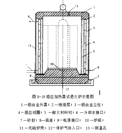
(3) Furnace type improvement: Change the pit type furnace type to a bell-type furnace to undertake the annealing function, cancel the resistance heating element of the bell-type furnace, change it to an induction coil, use induction heating, and cancel
 The heat-resistant steel liner of the bell furnace is lined with refractory materials. The supporting frame of the induction coil adopts the combined structure of insulating plate and aluminum alloy column. The power supply interface and the cooling water inlet and outlet interfaces are installed in the appropriate parts of the furnace shell. A fixed joint or interface is used inside the furnace shell. A water-cooled intermediate frequency cable is used outside the furnace shell to connect to the power supply interface, and a pressure hose for water supply is connected to the cooling water pipe. A furnace lining made of refractory material is used for isolation between the induction coil and the steel. The structure diagram of the other parts of the furnace is shown in Figure 8-19. Shielding gas can be fed into the furnace to reduce oxidation of the annealed steel. The heating temperature of the furnace is preferably 800°C, and a temperature measuring hole is provided in the middle of the furnace cover, and a thermocouple can be used to measure and control the furnace temperature.
