- 17
- Feb
How does the double-station drive shaft induction heating furnace quenching work?
How does the double-station drive shaft induction heating furnace quenching work?
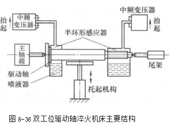
The drive shaft has two hardened parts, namely the flange rod and the spline. Due to the large output, the drive shaft medium frequency induction hardening machine tool is installed on the production line. The quenching of the induction heating furnace is a horizontal double station, and a semi-annular inductor is used to facilitate the in and out of the workpiece. Figure 8-36 shows the main structure of the double-station drive shaft induction heating furnace quenching. The main structure is two intermediate frequency transformers, two half-ring inductors, headstock, tailstock, stepping chain and lifting mechanism. The intermediate frequency power supply is 100kW and 10kHz. The two intermediate frequency transformers work alternately, and the left position heats the drive shaft. The flange and shaft, the right position heats the spline part. The two half-ring sensors allow the drive shaft of the lifting mechanism to enter the sensor without hindrance. The quenching transformer and the inductor can be turned up and down (take the intermediate frequency transformer side as a fulcrum, and perform a counterclockwise backward arc motion). In the lower position, the sensor just wraps the workpiece for heating; the rising position is the liquid sprayer Quench for the heated workpiece. Drive shaft intermediate frequency induction hardening process
As follows: The V-shaped groove of the lifting mechanism holds the drive shaft on the stepping chain in place; the tailstock top moves, tightens the workpiece, the spindle drives the workpiece to rotate, the left transformer is first connected to the power supply, and the workpiece flange and rod are heated. When the specified temperature is reached, the power is cut off; the left transformer rises, and the sprayer on the sensor starts to spray liquid; at the same time, the right transformer starts to power on, heats the spline part, and cuts off when the specified temperature is reached; the right transformer rises , The liquid sprayer on the sensor starts to spray liquid; the spline part begins to quench; then, the V-shaped groove of the lifting mechanism rises, the tailstock center is released, and the drive shaft drops onto the stepping chain with the V-shaped groove; stepping The chain moves, one step forward, the next drive shaft enters the position above the V-shaped groove, the drive shaft rises again, and so on.
The drive shaft on the production line is self-tempered by controlling the spray time. Since the next process requires machining and grinding, after the stepping chain moves 4 times, the drive shaft is cooled to room temperature for the second time.


