
- 14
- Sep
Tubing end induction အပူပေးကိရိယာ
Tubing end induction အပူပေးကိရိယာ
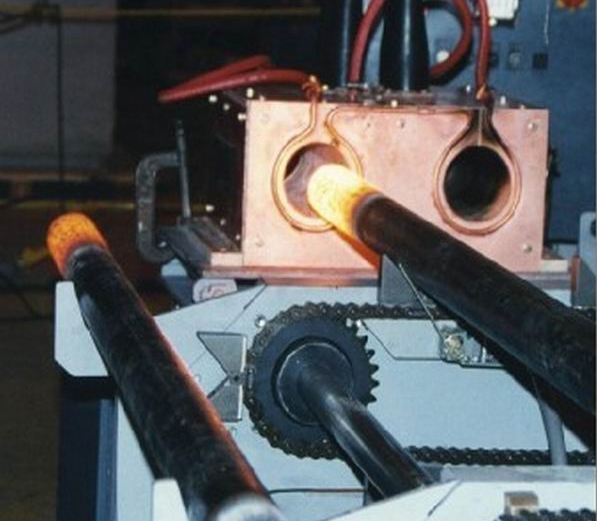
၁။ ဖွဲ့စည်းမှု သော induction အပူ device ကို ပိုက်ရဲ့အဆုံးမှာ
tubing end induction အပူပေးကိရိယာတွင် medium frequency induction heating furnace, capacitor cabinet, trolley, hydraulic cylinder, water pack, trolley, stainless steel towline, water and electric oil pipeline နှင့် intermediate frequency power cabinet တို့ပါ ၀ င်သည်။
ဤပစ္စည်းကိရိယာတွင်လက်တွန်းလှည်းနှစ်ချောင်းပါရှိပြီးတစ်ခုချင်းစီကိုမြေကြီးပေါ်တွင်ချထားသောရထားလမ်းပေါ်တွင်ထားရှိပြီးလူသားစွမ်းအားဖြင့်မောင်းနှင်ပြီးတည်နေရာပြဝက်အူကိရိယာပါရှိသည်။ တွန်းလှည်းတစ်ခုစီတွင်ကားငယ်တစ်စီးရှိသည်။ လက်တွန်းလှည်း၏ကိုယ်ထည်ကိုသံမဏိဖြင့်ဂဟေဆော်ပြီးတွန်းလှည်း၏ချောမွေ့သောရွေ့လျားမှုကိုရရှိစေရန်ဘီးငယ်သည် a -shaped groove wheel ဖြစ်သည်။ ကား၏ကိုယ်ထည်ကို worm lifter တပ်ဆင်ထားပြီး epoxy ပန်းကန်ဖြင့်ပြုလုပ်ထားသောအောက်ခြေပြားကြီးကို lifter ပေါ်တွင်တပ်ဆင်ထားသည်။ ကြမ်းပြင်ချောမွေ့စွာမြင့်တက်ခြင်းနှင့်ကျဆင်းခြင်းကိုသေချာစေရန်ကြီးမားသောကြမ်းပြင်နှင့်ကားကိုယ်ထည်ကို linear slide သံလမ်းများဖြင့်နေရာချထားသည်။ အလွှာအလယ်အလတ်ကြိမ်နှုန်း induction အပူမီးဖိုကိုအောက်ခြေပန်းကန်ပြားအဆုံးတစ်ခုစီတွင်တပ်ဆင်ထားသည်။ တွန်းလှည်းကိုဆလင်ဒါ၏တွန်းအားအောက်တွန်းလှည်းပေါ်တွင်သတ်မှတ်ထားသောလမ်းကြောင်းတစ်လျှောက်ရှေ့သို့နောက်ပြန်ရွှေ့နိုင်သည်။ အလယ်အလတ်ကြိမ်နှုန်း induction အပူပေးမီးဖိုကိုအောက်ခြေပန်းကန်ပြားလေးအားမူလီလေးခုဖြင့်တပ်ဆင်ထားသည်။ အောက်ခြေပန်းကန်ပြားကြီးကိုလက်ဖြင့်မြှင့်တင်ခြင်းဖြင့်မြှင့်နိုင်သည်၊ အောက်ခြေပန်းကန်ပြားငယ်သည်ဝါယာကြိုးမှတဆင့်ဖြတ်သွားနိုင်သည်။ ကြိမ်လုံးသည်အလုပ်လုပ်သည့်နေရာအလယ်အလတ်ကြိမ်နှုန်း induction အပူပေးမီး၏အလယ်ဗဟိုကိုချိန်ညှိရန်ဘယ်ညာရွေ့လျားသည်။ IF induction furnace တိုင်းတွင် capacitor cabinet တစ်ခုတပ်ဆင်ထားသည်။ capacitor cabinet ကို trolley ပေါ်တွင်တပ်ဆင်ထားပြီး၊ capacitor cabinet ကို medium-induction heating furnace မှတဆင့် medium-induction အပူပေးမီးဖိုနှင့်ချိတ်ဆက်ထားသည်။ ရေနှင့်ဆီပိုက်လိုင်း၏အဆုံးတစ်ဖက်ကိုလက်တွန်းလှည်းပေါ်ရှိကိရိယာများနှင့်ချိတ်ဆက်ထားပြီးအခြားတစ်ဖက်ကိုအလယ်အလတ်ကြိမ်နှုန်းပါဝါကက်ဘိနက်နှင့်ကတုတ်ကျင်းရှိရေပေးဝေရေးပိုက်တို့နှင့်ချိတ်ဆက်ထားသည်။ တွန်းလှည်းပေါ်မှ capacitor cabinet နှင့် intermediate frequency induction heating furnace နှင့် trolley နှင့် ground ကြားရေနှင့်ဆီဆက်သွယ်မှုကို stainless steel towline တွင်အသီးသီးတပ်ဆင်ထားသည်။
၂၊ ဆီပိုက်အဆုံး induction အပူပေးကိရိယာများ၏တည်ဆောက်ပုံ၊ လုပ်ဆောင်ချက်နှင့်လုပ်ဆောင်ချက်နိယာမ
အလုပ်၏အပူစုပ်ယူခြင်း၏နိယာမအားလျှပ်စစ်သံလိုက်ဓာတ်အားဖြင့်သူ့အလိုလို workpiece မှထုတ်လုပ်သောအပူအားဖြင့်အပူပေးသည်၊ ၎င်းတွင်အပူအလျင်အမြန်အပူပေးခြင်း၊ ယူနီဖောင်းအပူပေးခြင်း၊ မြင့်မားသောအပူထိရောက်မှုရှိခြင်းနှင့်ဓာတ်တိုးမှုဖြစ်စဉ်ပြန်လည်ထုတ်လုပ်နိုင်မှုစသည်တို့ဖြစ်သည်။ ကြိမ်နှုန်း induction အပူပေးမီးဖိုကိုသတ္ထုပစ္စည်းများဖိအားနှင့်အပူကုသမှု၏အပူလုပ်ငန်းစဉ်များတွင်တွင်ကျယ်စွာအသုံးပြုသည်။ အလတ်စားကြိမ်နှုန်း induction အပူပေးမီးဖိုကို induction coil၊ မီးဖိုအဖုံး၊ အထောက်အပံ့ခံဖွဲ့စည်းပုံနှင့်မီးဖိုခွံတို့ဖြင့်ဖွဲ့စည်းထားသည်။ induction coil ကိုစတုဂံပုံဖြတ်တောက်ထားသောကြေးနီပြွန်တစ်ခုနှင့်ပြုလုပ်ထားသည်။ ကြေးနီပြွန်ကိုလည်ပတ်နေစဉ်ရေဖြင့်အအေးခံသည်။ အထောက်အပံ့တည်ဆောက်ပုံနှင့်မီးဖိုခွံကိုသတ္ထုမဟုတ်သောပစ္စည်းများဖြင့်ပြုလုပ်ထားပြီးအမြင့်ခိုင်ခံ့မှု၊ အပူချိန်မြင့်မားမှုနှင့်မီးမလောင်ကျွမ်းနိုင်ချေ။
အပူပိုက်၏စွန်းများ၏ကွဲပြားခြားနားသောသတ်မှတ်ချက်များနှင့်ကိုက်ညီရန်ဤစက်ပစ္စည်းများစုစုပေါင်း ၁၈၀kw နှင့် ၂၂၀kw ပါ ၀ င်သောသတ်မှတ်ချက် ၂ မျိုးမှာအပူ 180. 220 စထရိကြိမ်နှုန်း induction furnace သည်အပူပိုက်၏အစွန်း၏ကွဲပြားခြားနားသောသတ်မှတ်ချက်များနှင့်ကိုက်ညီသည်။ နံပါတ် ၁ နံပါတ် ၁ မီးဖိုချောင်တွန်းလှည်းနှင့်အမှတ် ၂ မီးဖိုစွမ်းအားနှင့် ၁၈၀kw အသီးသီး ၂၂၀kw၊ နံပါတ် ၂ နံပါတ် ၃ မီးဖိုချောင်ရထားနှင့် ၄ င်းတို့အသီးသီးမီးဖိုသည် ၁၈၀kw နှင့် ၂၂၀kw အသီးသီးရှိကြသည်။ တွန်းလှည်းတစ်ခုစီတွင် IF induction မီးဖိုနှစ်ခု၏ဗဟိုအကွာအဝေးသည် ၁၂၀၀ မီလီမီတာနှင့်ဗဟိုသည်မြေပြင်အထက် ၁၀၀၀ မီလီမီတာရှိသည်။ မီးဖိုလေးလုံးစီတွင်၎င်း၏ကိုယ်ပိုင်အလယ်အလတ်ကြိမ်နှုန်းပါဝါကက်ဘိနက်နှင့် Capacitor Cabinet တို့တပ်ဆင်ထားသည်။ IF induction furnace ၁၆ လုံးသည် IF induction furnace ကိုလျင်မြန်စွာအစားထိုးနိုင်ရန်သေချာစေရန်တူညီသောအတိုင်းအတာများနှင့် mounting interfaces များရှိသည်။ ရ၊
3, the technical parameters of the medium frequency induction heating furnace for the end heating of the oil pipe
| နံပါတ် ၁ တွန်းလှည်း | နံပါတ် ၁ တွန်းလှည်း | မှတ်ချက်တွေ
|
|||
| No.1 အပူမီးဖို | အမှတ် ၂ အပူမီးဖို | No.3 အပူမီးဖို | No.4 အပူမီးဖို | ||
| Power က (KW) | 180 | 220 | 180 | ၄၊ | |
| ကြိမ်နှုန်း (khz) | 1.0 | 2.5 | 1.0 | 2.5 | |
| အပူအပူချိန် (° C) | အခန်းအပူချိန် ~ ၇၅၀ | 700to1250± 10 | 450 ~ 850 | ၈၀၀ မှ ၁၂၅၀ ± ၁၀ | |
| Cooling water volume (m3/h) | 15 | 15 | 15 | 15 | ပြင်ပရေလည်ပတ်မှု |
| အအေးရေဖိအား (Mpa) | ၆ မှ ၁၄ အထိ | 0.1 မှ 0.4 | 0.1 မှ 0.4 | 0.1 မှ 0.4 | |
4, tubing အပူကုကား
The trolley consists of an angle steel chassis with four slotted wheels and two upper and lower epoxy panels (silk plates). The upper plate is a small bottom plate with a thickness of 20 mm, and the lower plate is a large bottom plate with a thickness of 25 mm. The small bottom plate is mounted on the sliding shaft, and the sliding shaft is fixed on the large bottom plate. The lower part of the small bottom plate is provided with a nut, and the rotating screw can move the small bottom plate laterally. The large bottom plate is fixed to the worm lifter mounted on the chassis of the cart and is positioned by four linear slide rails. The lifter controls the large bottom plate to move up and down, and the small bottom plate moves up and down, so that the center of the sensor can be adjusted as required. A stainless steel bracket for fixing the drag chain is attached to the rear side of the lower panel, and the drag chain is fixed at the upper end of the bracket. The base of the trolley is welded with a support base connected to the oil cylinder, and under the action of the oil cylinder, the trolley can move forward and backward along the track. In this way, the intermediate frequency induction heating furnace mounted on the upper deck can adjust the position in the three-dimensional direction as required. The up and down and left and right trimming movements are manual, the front and rear movements are pushed by the cylinder, the stroke is controlled by the proximity switch, and the stroke length can be displayed on the scale fixed on the trolley. ,
5, tubing heating cylinder ၏အဆုံး
အပေါက်သည်φ ၆၃ မီလီမီတာနှင့်အမြင့်ဆုံးလေဖြတ်နိုင်မှုမှာ ၆၀၀ မီလီမီတာဖြစ်သည်။ ပိုက်နှင့်၎င်း၏ဆက်စပ်ပစ္စည်းများကို Guangzhou Agate Company မှရွေးချယ်သည်။ ဆလင်ဒါကိုတွန်းလှည်းမျက်နှာပြင်ပေါ်တွင်တပ်ဆင်ထားသည်။ ရေနံပိုက်လိုင်းသည်ဆွဲကြိုးမှတဆင့်ကတုတ်ကျင်းရှိအ ၀ င်နှင့်အထွက်ဆီပိုက်များနှင့်ချိတ်ဆက်ထားသည်။
Water bag group
ရေအိတ်အုပ်စုသည်အနောက်ဘက်နှင့်တွန်းလှည်း၏နှစ်ဖက်စလုံးတွင်တည်ရှိသည်။ ၎င်း၏လုပ်ဆောင်ချက်သည်တွန်းလှည်းပေါ်ရှိအလယ်အလတ်ကြိမ်နှုန်း induction အပူပေးမီးနှစ်လုံးနှင့်တွန်းလှည်းနှစ်လုံးပါ ၀ င်သောအအေးခံရေတို့ကိုစုဆောင်းရန်ဖြစ်သည်။ အလယ်အလတ်ကြိမ်နှုန်း induction အပူပေးမီးဖို၏အအေးခံရေအားရေစုပ်စက်နှင့်ရေအိတ်အုပ်စုကြီးမှရေခွဲစက်တို့ကမီးဖိုနှစ်လုံးထဲသို့မောင်းနှင်သည်။ မီးဖိုမှထွက်လာပြီးနောက်၎င်းသည်ကြီးမားသောရေအိတ်အဖွဲ့၏ရေစုပ်စက်ထဲသို့ ၀ င်သွားပြီးရေထွက်ပေါက်နှင့်ပိုက်လိုင်းကိုဖြတ်သွားသည်။ နောက်ဆုံးတွင်၎င်းသည်လည်ပတ်နေသောရေကန်သို့ပြန်လည်စီးဆင်းသည်။ ၎င်းသည် open loop ကိုပိုင်ဆိုင်သည်။ လျှပ်စစ် contact pressure gauge ကိုအလယ်အလတ်ကြိမ်နှုန်း induction heating furnace တစ်ခုစီ၏ water separator တွင်တပ်ဆင်ထားသည်။ ရေဖိအားသည်အလုပ်လုပ်သည့်ဖိအားထက်နိမ့်သောအခါမီးဖိုသည်အလိုအလျောက်ပိတ်သွားပြီးကွိုင်၏ရေပြတ်လပ်မှုကြောင့်ပစ္စည်းများပျက်စီးလိမ့်မည်မဟုတ်ပါ။ capacitor cabinet ၏အအေးခံရည်သည် cooling unit ၏ပျော့ပျောင်းသောရေမှလာသည်၊ ၎င်းသည်သေးငယ်သောရေအုပ်စုအုပ်စု၏ရေခွဲမှတဆင့် capacitor နှစ်ခုပါ ၀ င်သည်။ နောက်ဆုံးတွင်အအေးယူနစ်သို့ပြန်သွားသည်။ ၎င်းသည်ပိတ်ထားသောကွင်းတစ်ခုဖြစ်သည်။ ရေနှစ်ထုပ်၏အ ၀ င်နှင့်အထွက်ကိုဆွဲကြိုးရှိပိုက်များမှတဆင့်ကတုတ်ကျင်းရှိအ ၀ င်နှင့်အထွက်ဆိပ်ကမ်းများနှင့်အသီးသီးချိတ်ဆက်ထားသည်။
သြဇာရှိသောရေအားလုံးကိုကတုတ်ကျင်းရှိရေပိုက်အဆစ်တွင်အဆို့များနှင့်တပ်ဆင်သည်။
6, the end of the tubing heating set trolley
တွန်းလှည်းသည် ၀ န်၏အဓိကကိုယ်ထည်ဖြစ်ပြီးအဓိကအသုံးအဆောင်များကိုတွန်းလှည်းပေါ်တွင်တပ်ဆင်ထားသည်။ လက်တွန်းလှည်း၏အရွယ်အစားသည် ၂၇၀၀ * ၁၉၀၀ မီလီမီတာ ၂ နှင့်လက်တွန်းလှည်း၏မျက်နှာပြင်သည်မြေပြင်ထက် ၃၆၆ မီလီမီတာခန့်ရှိသည်။ တွန်းလှည်းကိုလူသားများကမောင်းနှင်ပြီးလေဖြတ်ခြင်းသည် ၂၈၀၀ မီလီမီတာထက်မပိုပါ။ လက်တွန်းလှည်းကိုနေရာယူပြီးနောက်လှည်းကိုနေရာချရန်ဝက်အူလေးချောင်းကိုဝက်အူဖြုတ်လိုက်သည်။ ရ၊
၇၊ အပူပေးပိုက်၏အဆုံးကိုသံမဏိသံမဏိဆွဲကြိုးဖြင့်တပ်ဆင်ထားသည်
တွန်းလှည်းနှင့်တွန်းလှည်းများ၏ရွေ့လျားမှု၌ပိုက်လိုင်း၏ထပ်တူပြုခြင်းနှင့်လုံခြုံစိတ်ချရမှုရှိစေရန်တွန်းလှည်းပေါ်မှ nozzles များနှင့်မြေပြင်ဆက်သွယ်မှု (ဟိုက်ဒရောလစ်ပိုက်များအပါအ ၀ င်) ကိုဆွဲကြိုးတစ်ခုဖြင့်ချိတ်ဆက်ထားသည်။ အဆုံးနှင့်တွန်းလှည်းအဆုံးသည်ရွှေ့ပြောင်းနိုင်သောအဆုံးဖြစ်သည်။ ကတုတ်ကျင်း -နောက်တွဲသံမဏိသံမဏိဆွဲကြိုးသည် TL125 III -300*350 ဖြစ်သည်။
တွန်းလှည်းပေါ်ရှိ capacitor cabinet နှင့် intermediate frequency induction heating furnace တို့အကြား water-cooled cable ကို drag ဆွဲကြိုးဖြင့်ချိတ်ဆက်ထားသည်။ capacitor cabinet end သည် fixed end ဖြစ်ပြီး၊ အလယ်အလတ်ကြိမ်နှုန်း induction heating မီးဖိုအဆုံးသည်ရွေ့နိုင်သောအဆုံးဖြစ်သည်။ Capacitor cabinet -medium frequency induction heating furnace stainless steel towline specification သည် TL95 III -150*250 ဖြစ်သည်။ တစ်ချိန်တည်းမှာပင်ကြီးမားသောရေအိတ်မှ medium medium induction heating furnace သို့ ၀ င်ထွက်သွားသောအအေးခံရေပိုက်ကိုလည်း drag chain ၌တပ်ဆင်ထားသည်။
၈၊ ပိုက်အဆုံးအပူတပ်ဆင်ခြင်းနှင့်ထိန်းသိမ်းခြင်း
၁။ အလတ်စားကြိမ်နှုန်း induction အပူပေးမီးဖိုကိုမအစားထိုးမီပါဝါကိုရပ်ပြီးရေအေးထားသောကေဘယ်ခရုကိုမဖယ်ရှားမီရေကိုရပ်လိုက်ပါ။
Quickly change the joint between the bolt and the water pipe. After the heating furnace is replaced, test the water leak first, and confirm that the joint does not leak water before it can be energized;
၂၊ ဆွဲကြိုး (သို့) ပြုတ်ကျနေသောဆွဲကြိုးများအတွက်မကြာခဏဆွဲကြိုးကိုစစ်ဆေးပါ။
၃၊ ဖြန့်ဝေနေသောရေကန်အားသန့်ရှင်း။ အပျက်အစီးများမရှိစေရန်ပိုက်လိုင်းထဲသို့အပျက်အစီးများမ ၀ င်စေဘဲပိတ်ဆို့စေပါသည်။
ကျပန်းပစ္စည်း
ထုတ်ကုန်အရည်အချင်းအသိအမှတ်ပြုလက်မှတ်;
ထုတ်ကုန်ထောက်ပံ့ရေးစာရင်း;
ထုပ်ပိုးစာရင်း;
ညွှန်ကြားချက်လက်စွဲ;
လျှပ်စစ်ဆိုင်ရာအစီအမံများနှင့်ညွှန်ကြားချက်များ၊
ကျပန်းထောက်ပံ့ရေးပုံများ
ကတုတ်ကျင်းပိုက်လိုင်းအပြင်အဆင်;
အပူပေးစက်၏ယေဘူယျပုံ
ပါဝါနှင့်မီးဖိုအပြင်အဆင်။