
- 14
- Sep
Indukčné vykurovacie zariadenia s hadicovými koncovkami
Indukčné vykurovacie zariadenia s hadicovými koncovkami
1. The composition of the indukčné vykurovacie zariadenie na konci hadičky
The tubing end induction heating equipment consists of medium frequency induction heating furnace, capacitor cabinet, trolley, hydraulic cylinder, water pack, trolley, stainless steel towline, water and electric oil pipeline and intermediate frequency power cabinet.
This set of equipment has two trolleys, each of which is placed on a rail laid on the ground, driven by human power, and has a positioning screw device. There is a small car on each trolley. The chassis of the trolley is welded by angle steel, and the small wheel is aV -shaped groove wheel to ensure the smooth movement of the trolley. The chassis of the car is equipped with a worm lifter, and a large bottom plate made of an epoxy plate is fixed on the lifter. To ensure the smooth rise and fall of the large floor, the large floor and the car chassis are positioned by linear slide rails. A medium-frequency induction heating furnace is installed at each end of the large bottom plate. The trolley can be moved forward and backward along the track fixed on the trolley under the push of the cylinder. The intermediate frequency induction heating furnace is fixed on the small bottom plate by four bolts. The large bottom plate can be raised or lowered by the manual lifter, and the small bottom plate can pass through the wire. The rod moves left and right to adjust the center of the intermediate frequency induction heating furnace in the working position. Each IF induction furnace is equipped with a capacitor cabinet. The capacitor cabinet is fixed on the trolley, and the capacitor cabinet is connected with the medium frequency induction heating furnace through a water-cooled cable. One end of the water and oil pipeline is connected to the equipment on the trolley, and the other end is connected to the water supply pipe joint in the intermediate frequency power cabinet and the trench. The connection between the capacitor cabinet on the trolley and the intermediate frequency induction heating furnace and the water and oil connection between the trolley and the ground are respectively installed in the stainless steel towline.
2, the structure, function and working principle of the oil pipe end induction heating equipment
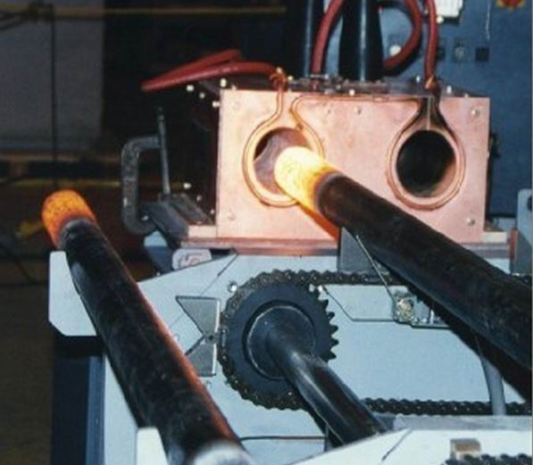
„Princíp indukčného ohrevu obrobku sa ohrieva teplom generovaným v obrobku samotným elektromagnetickou indukciou, čo má za následok rýchly ohrev, rovnomerné zahrievanie, vysokú účinnosť ohrevu a veľmi malú reprodukovateľnosť procesu oxidácie atď., Ktoré médium frekvenčne indukčná vykurovacia pec je široko používaná pri tlakovom spracovaní kovových materiálov a pri procese zahrievania tepelného spracovania. Stredofrekvenčná indukčná vykurovacia pec sa skladá z indukčnej cievky, obloženia pece, nosnej pevnej konštrukcie a plášťa pece. Indukčná cievka je vyrobená z medenej trubice s obdĺžnikovým prierezom. Medená rúrka je počas prevádzky chladená vodou; nosná konštrukcia a plášť pece sú vyrobené z nekovových materiálov s vysokou pevnosťou, odolnosťou voči vysokým teplotám a nehorľavosťou.
Toto zariadenie má celkový výkon 180 kW a 220 kW dva druhy špecifikácií 16 16 staničná frekvenčná indukčná pec na splnenie rôznych špecifikácií koncov vykurovacieho potrubia. 1, pecný výkon vozňa č. 1 a pec č. 2 a výkon 180 kw resp. 220 kw, pec č. 2 č. 3 pec a 4 výkon pece č. 180 je 220 kw a 1200 kw. Stredová vzdialenosť dvoch indukčných pecí IF na každom vozíku je 1000 mm a stred je 16 mm nad zemou. Každá zo štyroch pecí je vybavená vlastnou medzifrekvenčnou výkonovou skriňou a kondenzátorovou skriňou. XNUMX indukčných pecí IF má rovnaké rozmery a montážne rozhrania, aby bolo zaistené, že indukčnú pec IF je možné rýchlo vymeniť. ,
3, the technical parameters of the medium frequency induction heating furnace for the end heating of the oil pipe
| No. 1 trolley | No. 2 trolley | Poznámky
|
|||
| Č.1 vyhrievacia pec | Vykurovacia pec č. 2 | Č.3 vyhrievacia pec | Vykurovacia pec č.4 | ||
| Výkon (kw) | 180 | 220 | 180 | 220, | |
| Frekvencia (khz) | 1.0 | 2.5 | 1.0 | 2.5 | |
| Heating temperature (°C) | Room temperature ~750 | 700to1250± 10 | 450 ~ 850 | 800to1250±10 | |
| Cooling water volume (m3/h) | 15 | 15 | 15 | 15 | External circulation water |
| Cooling water pressure (Mpa) | 0.1to0.4 | 0.1 až 0.4 | 0.1 až 0.4 | 0.1 až 0.4 | |
4, the end of the tubing heating car
The trolley consists of an angle steel chassis with four slotted wheels and two upper and lower epoxy panels (silk plates). The upper plate is a small bottom plate with a thickness of 20 mm, and the lower plate is a large bottom plate with a thickness of 25 mm. The small bottom plate is mounted on the sliding shaft, and the sliding shaft is fixed on the large bottom plate. The lower part of the small bottom plate is provided with a nut, and the rotating screw can move the small bottom plate laterally. The large bottom plate is fixed to the worm lifter mounted on the chassis of the cart and is positioned by four linear slide rails. The lifter controls the large bottom plate to move up and down, and the small bottom plate moves up and down, so that the center of the sensor can be adjusted as required. A stainless steel bracket for fixing the drag chain is attached to the rear side of the lower panel, and the drag chain is fixed at the upper end of the bracket. The base of the trolley is welded with a support base connected to the oil cylinder, and under the action of the oil cylinder, the trolley can move forward and backward along the track. In this way, the intermediate frequency induction heating furnace mounted on the upper deck can adjust the position in the three-dimensional direction as required. The up and down and left and right trimming movements are manual, the front and rear movements are pushed by the cylinder, the stroke is controlled by the proximity switch, and the stroke length can be displayed on the scale fixed on the trolley. ,
5, koniec rúrkového ohrievacieho valca
The bore is φ 63 mm and the maximum stroke is 600 mm. The tubing and its accessories are selected from Guangzhou Agate Company. The cylinder is fixed on the trolley surface. The oil pipe is connected to the inlet and outlet oil pipes in the trench through the drag chain.
Water bag group
Skupina vodného vaku je umiestnená vzadu a na oboch stranách vozíka. Jeho funkciou je transport a zber chladiacej vody do dvoch stredofrekvenčných indukčných vykurovacích pecí a dvoch kondenzátorových skríň na vozíku. Chladiaca voda stredofrekvenčnej indukčnej vykurovacej pece je do dvoch pecí poháňaná vodným čerpadlom a odlučovačom vody skupiny veľkých vodných vakov. Potom, čo pec vystúpi, vstupuje do zberača vody skupiny veľkých vodných vakov a prechádza výstupom vody a potrubím. Nakoniec tečie späť do cirkulujúceho bazéna. Patrí do otvorenej slučky. Elektrický kontaktný tlakomer je inštalovaný na odlučovači vody každej medzifrekvenčnej indukčnej vykurovacej pece. Keď je tlak vody nižší ako pracovný tlak, pec sa automaticky vypne a zariadenie sa nepoškodí kvôli nedostatku vody v cievke. Chladiaca voda kondenzátorovej skrine pochádza z mäkkej vody chladiacej jednotky a vstupuje do dvoch kondenzátorových skriniek cez odlučovač vody skupiny malých zásobníkov vody, potom prúdi späť do zberača vody skupiny malých nádob s vodou a sa konečne vráti do chladiacej jednotky. Je to uzavretá slučka. Vstup a výstup dvoch balíkov vody sú príslušne spojené so vstupnými a výstupnými otvormi v priekope hadicami vlečnej reťaze.
Všetka tečúca voda je vybavená ventilmi na spojoch vodovodného potrubia v priekope.
6, the end of the tubing heating set trolley
Vozík je hlavným telesom nákladu a hlavné zariadenie je nainštalované na vozíku. Veľkosť vozíka je 2700 1900 * 2 366 mm 2800 a povrch vozíka je asi XNUMX mm nad zemou. Vozík poháňa človek a zdvih nie je menší ako XNUMX XNUMX mm. Potom, čo je vozík na svojom mieste, odskrutkujte štyri skrutky, aby sa vozík umiestnil. ,
7, koniec zahrievania rúrok je nastavený na ťažné lano z nehrdzavejúcej ocele
Aby bola zaistená synchronizácia a bezpečnosť potrubia pri pohybe vozíka a vozíka, všetky dýzy na vozíku a uzemnenie (vrátane hydraulickej hadice) sú spojené vlečnou reťazou, koniec výkopu je pevný koniec vozíka a koniec vozíka je pohyblivý. Ťažné zariadenie z nehrdzavejúcej ocele zákopu a prívesu je TL125 III -300*350.
Vodou chladený kábel medzi kondenzátorovou skriňou na vozíku a stredofrekvenčnou indukčnou vykurovacou pecou je tiež spojený vlečným reťazcom. Koniec skrine kondenzátora je pevný koniec a koniec medzifrekvenčnej indukčnej vykurovacej pece je pohyblivý. Kondenzátorová skrinka -stredofrekvenčná indukčná vykurovacia pec, špecifikácia vlečného vedenia z nehrdzavejúcej ocele je TL95 III -150*250. Hadica chladiacej vody, ktorá vstupuje do stredofrekvenčnej indukčnej vykurovacej pece z veľkého vodného vaku a vystupuje z nej, je zároveň inštalovaná aj v ťažnom reťazci.
8, tubing end heating installation and maintenance
1. Pred výmenou stredne frekvenčnej indukčnej vykurovacej pece vypnite napájanie a zastavte vodu pred odstránením vodou chladeného káblového slimáka.
Quickly change the joint between the bolt and the water pipe. After the heating furnace is replaced, test the water leak first, and confirm that the joint does not leak water before it can be energized;
2, často kontrolujte, či vlečná reťaz nie je zaseknutá alebo spadnutá;
3 , keep the circulating pool clean and free of debris, so as to prevent debris from entering the pipeline and causing blockage.
Random material
Osvedčenie o kvalifikácii výrobku;
Product supply list;
Baliaci zoznam;
Instruction Manual;
Electrical schematic and instructions;
Random supply drawings:
Trench piping layout;
General diagram of the heating machine;
Rozloženie energie a pece.