
- 14
- Sep
Оборудование для индукционного нагрева концов трубок
Оборудование для индукционного нагрева концов трубок
1. The composition of the устройство индукционного нагрева на конце трубки
The tubing end induction heating equipment consists of medium frequency induction heating furnace, capacitor cabinet, trolley, hydraulic cylinder, water pack, trolley, stainless steel towline, water and electric oil pipeline and intermediate frequency power cabinet.
This set of equipment has two trolleys, each of which is placed on a rail laid on the ground, driven by human power, and has a positioning screw device. There is a small car on each trolley. The chassis of the trolley is welded by angle steel, and the small wheel is aV -shaped groove wheel to ensure the smooth movement of the trolley. The chassis of the car is equipped with a worm lifter, and a large bottom plate made of an epoxy plate is fixed on the lifter. To ensure the smooth rise and fall of the large floor, the large floor and the car chassis are positioned by linear slide rails. A medium-frequency induction heating furnace is installed at each end of the large bottom plate. The trolley can be moved forward and backward along the track fixed on the trolley under the push of the cylinder. The intermediate frequency induction heating furnace is fixed on the small bottom plate by four bolts. The large bottom plate can be raised or lowered by the manual lifter, and the small bottom plate can pass through the wire. The rod moves left and right to adjust the center of the intermediate frequency induction heating furnace in the working position. Each IF induction furnace is equipped with a capacitor cabinet. The capacitor cabinet is fixed on the trolley, and the capacitor cabinet is connected with the medium frequency induction heating furnace through a water-cooled cable. One end of the water and oil pipeline is connected to the equipment on the trolley, and the other end is connected to the water supply pipe joint in the intermediate frequency power cabinet and the trench. The connection between the capacitor cabinet on the trolley and the intermediate frequency induction heating furnace and the water and oil connection between the trolley and the ground are respectively installed in the stainless steel towline.
2, the structure, function and working principle of the oil pipe end induction heating equipment
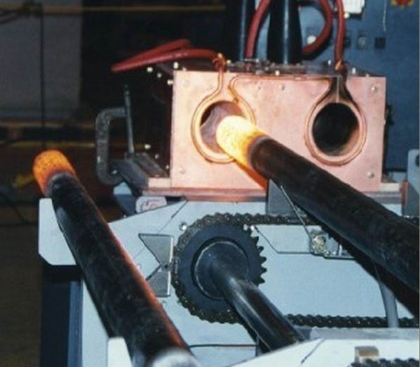
, Принцип индукционного нагрева заготовки нагревается за счет тепла, генерируемого в самой заготовке за счет электромагнитной индукции, это имеет нагрев, быстрый нагрев, равномерный нагрев, высокую эффективность нагрева и очень низкую воспроизводимость процесса окисления и т. Д., Что среда Частотная индукционная нагревательная печь широко используется при обработке металлических материалов под давлением и в процессе термической обработки. Среднечастотная индукционная нагревательная печь состоит из индукционной катушки, футеровки печи, несущей неподвижной конструкции и кожуха печи. Индукционная катушка изготовлена из медной трубки прямоугольного сечения. Медная трубка во время работы охлаждается водой; Несущая конструкция и кожух печи изготовлены из неметаллических материалов, обладающих высокой прочностью, высокой термостойкостью и негорючестью.
Это оборудование общей мощностью 180 кВт и 220 кВт два вида спецификаций 16 индукционная печь с частотой 16 станций для удовлетворения различных спецификаций концов нагревательной трубы. Мощность печи № 1 № 1 и мощность печи № 2 и 180 кВт соответственно 220 кВт, № 2 № 3 каретка и 4 мощность печи соответственно составляет 180 кВт и 220 кВт. Расстояние между центрами двух индукционных печей IF на каждой тележке составляет 1200 мм, а центр находится на высоте 1000 мм над землей. Каждая из четырех печей оборудована собственным шкафом питания промежуточной частоты и шкафом конденсаторов. Индукционные печи IF 16 имеют одинаковые размеры и монтажные интерфейсы, что обеспечивает быструю замену индукционной печи IF. ,
3, the technical parameters of the medium frequency induction heating furnace for the end heating of the oil pipe
| No. 1 trolley | No. 2 trolley | Замечания
|
|||
| No 1 нагревательная печь | Нагревательная печь No 2 | No 3 нагревательная печь | Нагревательная печь №4 | ||
| Мощность (кВт) | 180 | 220 | 180 | 220, | |
| Частота (кГц) | 1.0 | 2.5 | 1.0 | 2.5 | |
| Heating temperature (°C) | Room temperature ~750 | 700to1250± 10 | 450 ~ 850 | 800to1250±10 | |
| Cooling water volume (m3/h) | 15 | 15 | 15 | 15 | External circulation water |
| Давление охлаждающей воды (МПа) | 0.1to0.4 | С 0.1 до 0.4 | С 0.1 до 0.4 | С 0.1 до 0.4 | |
4, the end of the tubing heating car
The trolley consists of an angle steel chassis with four slotted wheels and two upper and lower epoxy panels (silk plates). The upper plate is a small bottom plate with a thickness of 20 mm, and the lower plate is a large bottom plate with a thickness of 25 mm. The small bottom plate is mounted on the sliding shaft, and the sliding shaft is fixed on the large bottom plate. The lower part of the small bottom plate is provided with a nut, and the rotating screw can move the small bottom plate laterally. The large bottom plate is fixed to the worm lifter mounted on the chassis of the cart and is positioned by four linear slide rails. The lifter controls the large bottom plate to move up and down, and the small bottom plate moves up and down, so that the center of the sensor can be adjusted as required. A stainless steel bracket for fixing the drag chain is attached to the rear side of the lower panel, and the drag chain is fixed at the upper end of the bracket. The base of the trolley is welded with a support base connected to the oil cylinder, and under the action of the oil cylinder, the trolley can move forward and backward along the track. In this way, the intermediate frequency induction heating furnace mounted on the upper deck can adjust the position in the three-dimensional direction as required. The up and down and left and right trimming movements are manual, the front and rear movements are pushed by the cylinder, the stroke is controlled by the proximity switch, and the stroke length can be displayed on the scale fixed on the trolley. ,
5, конец трубки нагревательного цилиндра
The bore is φ 63 mm and the maximum stroke is 600 mm. The tubing and its accessories are selected from Guangzhou Agate Company. The cylinder is fixed on the trolley surface. The oil pipe is connected to the inlet and outlet oil pipes in the trench through the drag chain.
Water bag group
Группа водяных мешков расположена сзади и с обеих сторон тележки. Его функция – подавать и собирать охлаждающую воду в две печи индукционного нагрева промежуточной частоты и два конденсаторных шкафа на тележке. Охлаждающая вода индукционной нагревательной печи промежуточной частоты подается в две печи водяным насосом и водоотделителем большой группы водяных мешков. После выхода из печи он попадает в водосборник большой группы водяных мешков и проходит через выпускное отверстие для воды и трубопровод. Наконец, он возвращается в циркулирующий бассейн. Он принадлежит к разомкнутому контуру. Электроконтактный манометр установлен на водоотделителе каждой печи индукционного нагрева промежуточной частоты. Когда давление воды ниже рабочего давления, печь автоматически отключается, и оборудование не будет повреждено из-за нехватки воды в змеевике. Охлаждающая вода конденсаторного шкафа поступает из мягкой воды охлаждающего устройства и поступает в два конденсаторных шкафа через водоотделитель небольшой группы водяных аккумуляторов, а затем возвращается в водосборник небольшой группы водяных аккумуляторов, и наконец возвращается в охлаждающую установку. Это замкнутый цикл. Впускной и выпускной патрубки двух водяных пакетов соответственно соединены с впускным и выпускным портами траншеи через шланги в тормозной цепи.
Вся поступающая вода снабжена клапанами на стыках водопроводных труб в траншее.
6, the end of the tubing heating set trolley
Тележка является основной частью груза, а основное оборудование устанавливается на тележке. Размер тележки составляет 2700 * 1900 мм 2, а поверхность тележки находится на высоте около 366 мм над землей. Тележка приводится в движение человеком, ход не менее 2800 мм. После того, как тележка поставлена на место, четыре винта откручиваются, чтобы установить тележку. ,
7, конец нагревательной трубки установлен с буксирным тросом из нержавеющей стали.
Чтобы обеспечить синхронизацию и безопасность трубопровода при движении тележки и тележки, все насадки на тележке и заземление (включая гидравлический шланг) соединены тросовой цепью, конец траншеи закреплен. конец, а конец тележки – подвижный конец. Траншея – прицепной трос из нержавеющей стали ТЛ125 III -300 * 350.
Кабель с водяным охлаждением между шкафом конденсаторов на тележке и печью индукционного нагрева промежуточной частоты также соединен тяговой цепью. Конец шкафа конденсатора является неподвижным концом, а конец печи индукционного нагрева промежуточной частоты – подвижным концом. Конденсаторный шкаф – среднечастотная печь индукционного нагрева, технические характеристики буксирного трубопровода из нержавеющей стали: TL95 III -150 * 250. В то же время шланг охлаждающей воды, который входит и выходит из печи среднечастотного индукционного нагрева из большого водяного мешка, также устанавливается в тормозной цепи.
8, tubing end heating installation and maintenance
1. Перед заменой печи среднечастотного индукционного нагрева выключите питание и остановите подачу воды, прежде чем снимать водоохлаждаемую кабельную улитку.
Quickly change the joint between the bolt and the water pipe. After the heating furnace is replaced, test the water leak first, and confirm that the joint does not leak water before it can be energized;
2, часто проверяйте тормозную цепь на предмет застрявших или упавших цепей;
3 , keep the circulating pool clean and free of debris, so as to prevent debris from entering the pipeline and causing blockage.
Random material
Сертификат квалификации продукции;
Product supply list;
Товарная накладная;
Instruction Manual;
Electrical schematic and instructions;
Random supply drawings:
Trench piping layout;
General diagram of the heating machine;
Power and furnace layout.