
- 22
- Sep
Steel rod continuous induction heating furnace
Steel rod continuous induction heating furnace
In steel and machinery manufacturing plants, when the output is large, the continuous induction heating method for steel bars is now used more. After the steel rod is heated, it is subjected to hot shearing, and then die forging or stamping.
Figure 12-51 is a set of steel rod intermediate frequency continuous induction heating furnace. The steel rod is placed on the vibrating platform of the feeding rack, and is pulled to the feeding raceway through the automatic pulling mechanism, which is driven by a stepless speed regulation DC motor. The feed roller feeds the bar to the inductor for induction heating. The number of sensors is determined according to the diameter of the bar and the output. These sensors are arranged in a straight line. This continuous induction heating furnace is used to heat steel bars with a length of Φ55 – Φ 100 mm and a length of 6m . The heating temperature is t = 1200℃±25Y, that is, the temperature difference between the surface and the core of the bar is 50℃, and the productivity is 3600kg/h. The thyristor inverter is powered, the frequency is 1100Hz, the power is 1 320kW, and the relevant parameters of the inductor are shown in Table 12-10 .
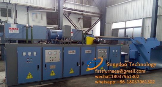
Figure 12-51 Continuous induction heating furnace
Table 12-10 Technical parameters of the sensor
| Steel rod diameter /mm | Φ 55 – Φ 65 | Φ 70 – Φ 80 | Φ 85 – Φ 100 |
| Coil turns/turn | 31 | 27 | 27 |
| Coil inner diameter /mm | Φ 110 | Φ 130 | Φ 155 |
| Lining inner diameter /mm | Φ 90 | Φ 105 | Φ 125 |
| Pure copper pipe size /mm | 16 x 16 | 14 X14 | 14 X14 |
| Coil waterway/a | 2 | 2 | 2 |
| Voltage/V | 325 | 325 | 325 |
| Current /A | 2700 | 2600 | 2400 |
| Current frequency /Hz | 1100 | 1100 | 1100 |
The inductors are divided into three groups according to the diameter of the steel rods. When heating steel rods of different diameters, the corresponding inductors must be replaced. Up to 10 inductors can be installed on the induction heating furnace . The coil length of the inductor is 550mm. After insulation treatment, the coil is lined with a heat-insulating layer made of mineral wool and a heat-resistant layer made of refractory materials. Finally, an asbestos cement board is used to make a box, and the coil is fixed in the box. . The length of each box is 600mm, the installation distance between the box and the box is 200mm, and the feeding support spoke is installed in between.
The power supply of the inductor is that the two inductors are connected in series first, and then connected in parallel on the power supply line, as shown in Figure 12-52 .
Figure 12-53 is a continuous induction heating production line manufactured by a foreign company with a power of 12MW, a total of 26 inductors, and a total length of 157 m (47.86m) .
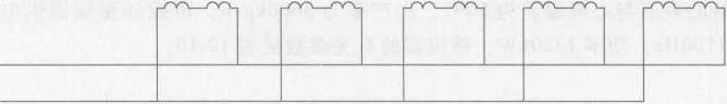
Figure 12-52 Wiring diagram of 10 sensors
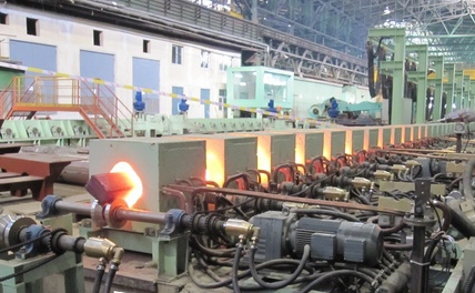
Figure 12-53 Continuous induction heating production line