
- 19
- Feb
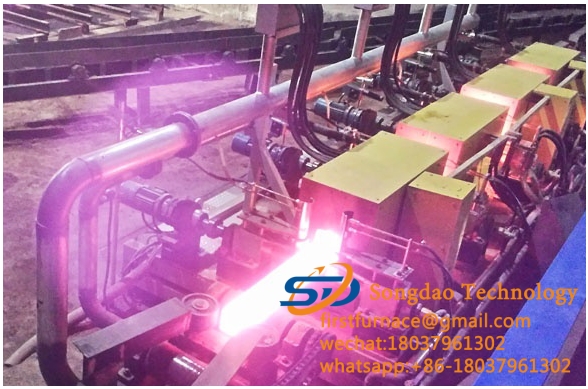
鋼管焼入れ焼戻し生産ラインの構成と機能
1. Loading platform
The loading platform is a stack of steel pipes to be heated. The platform is welded by 16mm thick steel plate and 20 hot-rolled I-beam. The width of the platform is 200mm, and the platform has a 2.4° inclination. It can hold 8 φ325 steel pipes, the platform and the column. It is connected by bolts. When working, the crane can hoist the whole bundle onto the platform, and the bulk bundle device feeds the material. The bulk bundle device is driven by an air cylinder. After the bundle is loosened, the heated steel pipes will automatically roll to the platform one by one and separate them. At the material position, the separation mechanism will send out and roll the material to the end of the loading platform under the control of the beat. The end is equipped with a blocking positioning seat to block the material and position it in the V-shaped groove.
2. Feeding translation mechanism
The feed translation mechanism is hydraulically driven, with 6 sets of supporting mechanisms and 6 sets of metallurgical cylinders with a diameter of φ50 and a stroke of 300mm. In order to ensure synchronization, 6 sets of hydraulic cylinders are equipped with hydraulic motors. Two sets of translational oil cylinders have a bore of φ80 and a stroke of 750mm. Translation into place, exactly at the center of the double rollers. Each set of double roller supporting mechanism is equipped with 4 wheel sets, and two 11# light rails are supported under the wheel sets, which are accurate, labor-saving, practical and reliable.
3. Double support rod transmission system
The double support rod transmission device, by adjusting the angle of the double support rod, can not only realize the speed of the steel pipe rotation but also ensure the forward speed. The double support rod transmission device adopts a reducer and a frequency converter to ensure the forward speed requirements of steel pipes of different diameters. There are 38 groups of double support bars, 12 groups at the feed end, 14 groups at the middle section, and 12 groups at the discharge end. The distance between the supporting rollers is 1200mm, the center distance between the two wheels is 460mm, and the roller diameter is 450mm. It takes into account the φ133~φ325 heating steel pipe. One group of rollers is the power wheel and the other group is the supporting driven wheel. Considering that the heating furnace has a certain installation Position and power wheels are designed with a set of 1:1 sprocket chain transmission device, the purpose of which is to move the center distance of the transmission connection by 350mm. All heating and discharging areas are equipped with water cooling device on the supporting roller rotation axis, and the supporting roller adopts bearings. In order to ensure the uniform and balanced transmission speed of the workpiece before and after, 38 frequency conversion motors are used for the power. The speed of the motor is controlled by the frequency converter. The supporting roller speed range: 10~35 rpm, forward speed 650~2500mm/min, frequency converter speed adjustment range: 15~60Hz. The supporting roller is placed at an angle of 5° with the center. The maximum angle can be adjusted to 11°, and the minimum can be adjusted to 2°. The angle of the supporting roller is adjusted by the electric motor to drive the turbine worm to be adjusted separately in three areas.
一体型ダブルサポートロッド伝達装置は、供給端から排出端まで0.5%傾斜したテーブルに設置されており、焼入れ後に鋼管に残った水をスムーズに排出することができます。
By controlling the speed of the feeding roller, the heating zone support roller, and the discharge support roller, the steel pipes are connected to each other and enter and exit each section of the heating furnace. The steel pipes that are connected end to end are automatically separated before being put on the cooling bed.
4. Heating furnace cooling system
無錫アークのFL-1500BPウィンドウォータークーラーは、炉本体の冷却に使用されます。 FL-500ウィンドウォータークーラーは、新しく追加された1500Kw(750つのXNUMXKw)電源を個別に冷却します(冷却水パイプはステンレス鋼でできています)。
FL-1500BPタイプのウィンドウォータークーラー(冷却炉本体)のパラメーター:
冷却能力:451500kcal / h; 使用圧力:0.35Mpa
Working flow: 50m3/h; inlet and outlet pipe diameter: DN125
Rated power of fan: 4.4Kw; rated power of water pump: 15Kw
FL-500 wind water cooler (cooling power supply) parameters:
冷却能力:151500kcal / h; 使用圧力:0.25Mpa
Working flow: 20m3/h; inlet and outlet pipe diameter: DN80
Rated power of fan: 1.5Kw; rated power of water pump: 4.0Kw
5.液体冷却システムの急冷
Use the FL-3000BPT wind-water cooler of Wuxi Ark to cool the furnace body:
FL-3000BPT type wind water cooler (cooling furnace body) parameters:
冷却能力:903000kcal / h; 使用圧力:0.5Mpa
Working flow: 200m3/h; inlet and outlet pipe diameter: DN150
ファンの定格電力:9.0Kw; 送水ポンプの定格出力:30Kw×2
6.排出物の持ち上げおよび並進機構
排出リフトおよび並進機構は、油圧シリンダーをホットゾーンから遠ざけるためにレバータイプを採用しています。 加熱鋼管の真直度を確保するために、排出リフトおよび並進装置は、11つの本体に結合された11グループの支持機構を備えています。 160グループの支持機構が同時に材料を持ち上げたり下ろしたりすることができ、鋼管の加熱の同期を確実にします。 吊り上げには360セットの冶金シリンダーφ80×1200を使用し、並進シリンダーにはXNUMXセットのφXNUMX×XNUMXを使用します。 ストロークコントロールには近接スイッチが装備されており、調整することができます。 油圧シリンダには断熱保護板が付いています。
7.双方向冷却ベッド
The cooling bed adopts two sets of sprocket chain transmission mechanism, one is a dragging and pulling device, and the other is a dragging and rotating device.
The chain drag rotation device, the overall plane height of the chain is slightly higher than the chain plane height of the drag pull device, and the chain drag rotation device moves with the steel pipe to rotate at a uniform speed. So as to prevent the deformation caused by the steel pipe stopping at a certain point and not rotating. The motor power is 15Kw, and the temperature after the cooling bed is ≤150℃.
ドラッグアンドプル装置のチェーンは自作チェーンを採用しています。 各コンベヤチェーンには、20セットのスクレーパーポジショニングラックが装備されています。 移動モードは、段階的なドラッグ方法です。 ラチェット機構を採用しています。 チェーンとチェーンの中心距離は1200mmです。 全部で11セットあります。 ルート、ドラッグジッパーデバイスは鋼管の重量を支えていません。
加熱された鋼管との長時間の接触により、ドライブチェーンは熱を発生し、チェーンに望ましくない要因を長期間引き起こします。 この隠れた危険を排除するために、引きずり回転装置の中央にプールを構築し、引きずり回転装置のチェーンを構築しました。 移動しながら冷やす。
8. Collecting platform
ベンチは断面鋼で溶接されています。 ベンチは16mm厚の鋼板と20本の熱間圧延Iビームで溶接されています。 ベンチの幅は200mmです。 ベンチの傾斜は2.4°です。 それは7つのφ325鋼管を保持することができます。 ベンチと支柱はボルトで接続されています。 スタンド間の距離は1200mmで、スタンドの端には鋼管リミットストップアームが装備されています。
収集台の端に赤外線温度計を設置し、鋼管下の冷却床後の温度を測定し、測定データの最大値を上位のコンピューターに送信します。
9.加熱炉調整ブラケット
ガイドコラムカバーの電動調整、昇降。 XNUMX組のスパイラルエレベータはギア減速機で駆動されて高さを調整し、リフトは安定していて信頼性があります。
10.ブロッキングメカニズム
鋼管を急冷、正規化、焼き戻しした後、すぐに端に達すると、ここの遮断機構によって遮断されます。 近接スイッチが信号を受信すると、排出リフトおよび並進機構が作動し、チェーンが回転装置を引きずって作動を停止します。 持ち上げおよび並進機構が材料を冷却床に送り、それを着実に下ろすと、チェーンが回転装置のモーターを引きずって再起動します。
11.油圧ステーション
The working pressure is 16Mpa and the volume is 500ml.
主な構成:ダブル電動ダブルポンプ、電動制御弁、圧力調整弁、油面表示、油温計、油圧計、油水ラジエーター等。油圧管はすべてステンレス鋼管で、油圧油タンクはステンレス鋼板で溶接。
11. Quenching liquid spray system
二極空気水ミスト噴霧システム、二極水噴霧システム、および一段空気噴霧乾燥システムを採用して、一体型噴霧システムを形成する。 すべての調整は、産業用コンピューターと電気比例制御バルブを介して自動的に行われます。
12. Quenching liquid collection system
Use the online collection tank to complete the corresponding quenching liquid collection pool. A filter collection net is installed in the collection tank to facilitate cleaning of impurities.
13.アンチスタックパイプシステムシステム
供給端のXNUMX本の支持棒の間に速度測定装置を追加して、チューブが詰まっているか(チューブが動かない)かを検出し、チューブが詰まるとアラーム信号を発します。 本装置と送り検出スイッチ信号は同じ信号です。
電圧安定化システム
The method of detecting the grid voltage is adopted. When the grid voltage changes, the output power of the intermediate frequency power supply is automatically adjusted to ensure the stability of the heating temperature. In addition, when the grid voltage changes by ±10%, the intermediate frequency voltage changes only Is 1%.