
- 19
- Feb
Composition and function of steel pipe quenching and tempering production line
Composition and function of steel pipe quenching and tempering production line
1. Loading platform
The loading platform is a stack of steel pipes to be heated. The platform is welded by 16mm thick steel plate and 20 hot-rolled I-beam. The width of the platform is 200mm, and the platform has a 2.4° inclination. It can hold 8 φ325 steel pipes, the platform and the column. It is connected by bolts. When working, the crane can hoist the whole bundle onto the platform, and the bulk bundle device feeds the material. The bulk bundle device is driven by an air cylinder. After the bundle is loosened, the heated steel pipes will automatically roll to the platform one by one and separate them. At the material position, the separation mechanism will send out and roll the material to the end of the loading platform under the control of the beat. The end is equipped with a blocking positioning seat to block the material and position it in the V-shaped groove.
2. Feeding translation mechanism
The feed translation mechanism is hydraulically driven, with 6 sets of supporting mechanisms and 6 sets of metallurgical cylinders with a diameter of φ50 and a stroke of 300mm. In order to ensure synchronization, 6 sets of hydraulic cylinders are equipped with hydraulic motors. Two sets of translational oil cylinders have a bore of φ80 and a stroke of 750mm. Translation into place, exactly at the center of the double rollers. Each set of double roller supporting mechanism is equipped with 4 wheel sets, and two 11# light rails are supported under the wheel sets, which are accurate, labor-saving, practical and reliable.
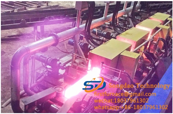
3. Double support rod transmission system
The double support rod transmission device, by adjusting the angle of the double support rod, can not only realize the speed of the steel pipe rotation but also ensure the forward speed. The double support rod transmission device adopts a reducer and a frequency converter to ensure the forward speed requirements of steel pipes of different diameters. There are 38 groups of double support bars, 12 groups at the feed end, 14 groups at the middle section, and 12 groups at the discharge end. The distance between the supporting rollers is 1200mm, the center distance between the two wheels is 460mm, and the roller diameter is 450mm. It takes into account the φ133~φ325 heating steel pipe. One group of rollers is the power wheel and the other group is the supporting driven wheel. Considering that the heating furnace has a certain installation Position and power wheels are designed with a set of 1:1 sprocket chain transmission device, the purpose of which is to move the center distance of the transmission connection by 350mm. All heating and discharging areas are equipped with water cooling device on the supporting roller rotation axis, and the supporting roller adopts bearings. In order to ensure the uniform and balanced transmission speed of the workpiece before and after, 38 frequency conversion motors are used for the power. The speed of the motor is controlled by the frequency converter. The supporting roller speed range: 10~35 rpm, forward speed 650~2500mm/min, frequency converter speed adjustment range: 15~60Hz. The supporting roller is placed at an angle of 5° with the center. The maximum angle can be adjusted to 11°, and the minimum can be adjusted to 2°. The angle of the supporting roller is adjusted by the electric motor to drive the turbine worm to be adjusted separately in three areas.
The integral double support rod transmission device is installed on a 0.5% inclined table from the feeding end to the discharging end, so that the water remaining in the steel pipe after quenching can be smoothly discharged.
By controlling the speed of the feeding roller, the heating zone support roller, and the discharge support roller, the steel pipes are connected to each other and enter and exit each section of the heating furnace. The steel pipes that are connected end to end are automatically separated before being put on the cooling bed.
4. Heating furnace cooling system
The FL-1500BP wind-water cooler of Wuxi Ark is used to cool the furnace body. The FL-500 wind water cooler separately cools the newly added 1500Kw (two 750Kw) power sources (the cooling water pipe is made of stainless steel):
FL-1500BP type wind water cooler (cooling furnace body) parameters:
Cooling capacity: 451500kcal/h; working pressure: 0.35Mpa
Working flow: 50m3/h; inlet and outlet pipe diameter: DN125
Rated power of fan: 4.4Kw; rated power of water pump: 15Kw
FL-500 wind water cooler (cooling power supply) parameters:
Cooling capacity: 151500kcal/h; working pressure: 0.25Mpa
Working flow: 20m3/h; inlet and outlet pipe diameter: DN80
Rated power of fan: 1.5Kw; rated power of water pump: 4.0Kw
5. Quenching liquid cooling system
Use the FL-3000BPT wind-water cooler of Wuxi Ark to cool the furnace body:
FL-3000BPT type wind water cooler (cooling furnace body) parameters:
Cooling capacity: 903000kcal/h; working pressure: 0.5Mpa
Working flow: 200m3/h; inlet and outlet pipe diameter: DN150
Rated power of fan: 9.0Kw; rated power of water pump: 30Kw×2
6. Discharge lifting and translation mechanism
The discharging lift and translation mechanism adopts the lever type to keep the hydraulic cylinder away from the hot zone. In order to ensure the straightness of the heating steel pipe, the discharging lifting and translation device is equipped with 11 groups of supporting mechanisms, which are combined into one body. 11 groups of supporting mechanisms can hold up and put down the material at the same time, ensuring the synchronization of the heating of the steel pipe. Two sets of metallurgical cylinders φ160×360 are used for lifting, and two sets of φ80×1200 are used for translation cylinders. The stroke control is equipped with a proximity switch and can be adjusted. The hydraulic cylinder is equipped with a heat-insulating protective plate.
7. Two-way cooling bed
The cooling bed adopts two sets of sprocket chain transmission mechanism, one is a dragging and pulling device, and the other is a dragging and rotating device.
The chain drag rotation device, the overall plane height of the chain is slightly higher than the chain plane height of the drag pull device, and the chain drag rotation device moves with the steel pipe to rotate at a uniform speed. So as to prevent the deformation caused by the steel pipe stopping at a certain point and not rotating. The motor power is 15Kw, and the temperature after the cooling bed is ≤150℃.
The chain of the drag and pull device adopts self-made chains. Each conveyor chain is equipped with 20 sets of scraper positioning racks. The movement mode is a step-by-step dragging method. It adopts a ratchet mechanism. The center distance between the chain and the chain is 1200mm. There are 11 sets in total. Root, the drag zipper device does not carry the weight of the steel pipe.
Due to the long-term contact with the heated steel pipe, the drive chain will generate heat, which will cause undesirable factors to the chain for a long time. In order to eliminate this hidden danger, a pool was built in the center of the dragging and rotating device, so that the chain of the dragging and rotating device was built. Cool while moving.
8. Collecting platform
The bench is welded by section steel. The bench is welded with 16mm thick steel plate and 20 hot-rolled I-beam. The width of the bench is 200mm. The bench has a 2.4° inclination. It can hold 7 φ325 steel pipes. The bench and the column are connected by bolts. The distance between the stand is 1200mm, and the end of the stand is equipped with a steel tube limit stop arm.
An infrared thermometer is installed at the end of the collecting platform to measure the temperature after the cooling bed under the steel pipe, and send the maximum value of the measured data to the upper computer.
9. Heating furnace adjustment bracket
Electric adjustment, lifting and lowering of the guide column cover. Two sets of spiral elevators are driven by a gear reducer to adjust the height, and the lifting is stable and reliable.
10. Blocking mechanism
After the steel pipe is quenched, normalized, and tempered, when it reaches the end quickly, it is blocked by the blocking mechanism here. When the proximity switch receives the signal, the discharge lifting and translation mechanism works, and the chain drags the rotating device to stop working . When the lifting and translation mechanism sends the material to the cooling bed and puts it down steadily, the chain drags the motor of the rotating device to restart.
11. Hydraulische post
The working pressure is 16Mpa and the volume is 500ml.
Main configuration: double electric double pump, electric control valve, pressure regulating valve, oil level display, oil temperature gauge, oil pressure gauge, oil-water radiator, etc. The hydraulic pipes are all stainless steel pipes, and the hydraulic oil tank is welded by stainless steel steel plates.
11. Quenching liquid spray system
Adopt two-pole air-water mist spray system, two-pole water spray system, and one-stage pneumatic spray drying system to form an integral spray system. All adjustments are done automatically through industrial computer and electric proportional control valve.
12. Quenching liquid collection system
Use the online collection tank to complete the corresponding quenching liquid collection pool. A filter collection net is installed in the collection tank to facilitate cleaning of impurities.
13. Anti-stuck pipe system system
A speed measuring device is added between the two supporting rods at the feeding end to detect whether the tube is stuck (the tube does not move), and an alarm signal is issued once the tube is stuck. This device and the feed detection switch signal are the same signal.
Voltage stabilization system
The method of detecting the grid voltage is adopted. When the grid voltage changes, the output power of the intermediate frequency power supply is automatically adjusted to ensure the stability of the heating temperature. In addition, when the grid voltage changes by ±10%, the intermediate frequency voltage changes only Is 1%.