
- 15
- Feb
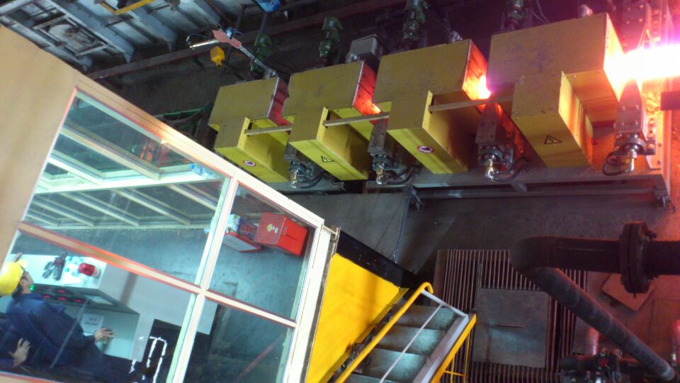
Kompletny zestaw urządzeń do nagrzewania indukcyjnego do podnoszenia temperatury rur stalowych
Kompletny zestaw urządzeń do nagrzewania indukcyjnego do podnoszenia temperatury rur stalowych
1. Główne parametry i wymagania marki kompletnego zestawu urządzeń do nagrzewania indukcyjnego do podnoszenia temperatury rur stalowych
Główne wyposażenie tego systemu grzewczego składa się z dwóch sześciofazowych transformatorów prostowniczych 2000KVA, dwóch dwunastopulsowych zasilaczy rezonansowych pośredniej częstotliwości o mocy 1500KW/1500Hz, dwóch szaf kondensatorowych i dwóch kompletów cewek (po 6 kompletów), o łącznej mocy 3000KW. System automatycznej kontroli temperatury składa się z komputera przemysłowego Advantech, sterownika Siemens S7-300, trzech zestawów dwukolorowych termometrów na podczerwień firmy Raytek, trzech zestawów przełączników fotoelektrycznych Turck i dwóch zestawów urządzeń do pomiaru prędkości BALLUFF. Oprogramowanie do sterowania przemysłowego jest oprogramowaniem autoryzowanym przez firmę Siemens.
2. Process parameter requirements
A. Steel pipe specifications:
Φ133×14 4.5m długości (rzeczywista średnica zewnętrzna jest kontrolowana poniżej Φ135)
Φ102×12 3~4.0m length (the actual outer diameter is controlled below Φ105)
Φ72×7 4.5m długości (rzeczywista średnica zewnętrzna jest kontrolowana poniżej Φ75)
B. Steel pipe material: TP304, TP321, TP316, TP347, P11, P22, etc.
C. Heating temperature: about 150℃, the temperature before the stainless steel tube enters the furnace: the head is about 920~950℃, the tail is about 980~1000℃, and the internal temperature of the pipe is higher than the external temperature), the low temperature end is required to be heated and the whole The temperature is raised to (1070~1090) ℃ at the head and tail, and the temperature difference between the head and tail is controlled within 30 degrees when it is out of the furnace.
D. Maksymalne wygięcie rury stalowej (prostość): 10mm/4500mm
F. Heating speed: ≥0.30m~0.45m/sm/s
E. Heating process control: the uniformity of the discharge temperature should be ensured, and the deformation of the pipe should be reduced. The furnace body has a total of 6 sections, each section is about 500mm in length (each power supply controls the heating of 3 sections of the furnace body). At the entrance and exit of each group of furnaces Two-color thermometers are installed for temperature measurement, speed measurement devices are installed for speed measurement, and closed-loop temperature control is realized. Reliable and optimized control algorithms are used. After temperature simulation data collection and processing, data calculation, dynamic adjustment and precise control of the output of each group of furnace bodies Power, to ensure that the discharge temperature of different specifications of tube blanks tends to be consistent, and the uniformity is better, and it overcomes the danger of microscopic cracks caused by thermal stress.
Dodatkowo, w celu wyrównania różnicy czasu pomiaru temperatury termometrem i poprawienia czułości sterowania, na wejściu i wyjściu każdej grupy pieców zainstalowano urządzenie do wykrywania gorącego ciała, aby piec grzewczy był bardziej czuły i niezawodne w utrzymywaniu mocy i wysokiej mocy przełączania między materiałami niewypełnionymi i wypełnionymi.
3. Six-phase rectifier transformer parameters and functional requirements:
The whole set of equipment uses two 2000KVA rectifier transformers, each with a 12-pulse rectifier structure. The main parameters are as follows:
Pojemność znamionowa: Sn=2000KVA
Napięcie pierwotne: U1=10KV 3φ 50Hz
Secondary voltage: U2=660V
Connection group: d/d0, Y11
Wydajność: η ≥ 98%
Cooling method: oil-immersed natural cooling
Protection function: heavy gas trip, light gas trip, pressure release switch, oil over-temperature alarm
With ±5%, 0% three-stage voltage regulation on the high-pressure side
4. The main parameters and functional requirements of the intermediate frequency power supply for the complete set of steel pipe temperature raising induction heating equipment:
Napięcie wejściowe: 660V
Napięcie DC: 890V
Prąd DC: 1700A
Napięcie częstotliwości pośredniej: 1350V
Częstotliwość pośrednia: 1500Hz
Intermediate frequency power: 1500KW/each
5. Wymagania dotyczące szafy kondensatorowej
a, capacitor selection
Elektryczny kondensator grzewczy 1500 Hz produkowany przez fabrykę kondensatorów mocy Xin’anjiang
Numer modelu: RFM2 1.4-2000-1.5S
Kondensator jest zainstalowany pod ramą pieca około 500 mm poniżej podłogi ramy pieca, głębokość wykopu jest większa niż 1.00 metra, a szerokość wykopu wynosi 1.4 metra.
b. Water cooling pipeline requirements
Made of thick-walled stainless steel, 3.5-inch water inlet pipe, 4-inch water return pipe, and other 2.5-inch pipes, including stainless steel pipe fittings and switches.
6. Wymagania dotyczące cewki indukcyjnej i pieca
Dwa końce korpusu pieca przyjmują miedziane płyty ochronne, aby zmniejszyć wyciek magnetyczny i projekt przepływu wody na obwodzie wlotu pieca. Obudowa wykonana jest z niemagnetycznej stali nierdzewnej. Rura miedziana jest nawinięta miedzią beztlenową T2, grubość ścianki rury miedzianej jest większa lub równa 2.5 mm, a materiał izolacyjny korpusu pieca jest wykonany z materiału wiążącego American Union Ore, który ma wysoką wytrzymałość i wysoką temperaturę odporność i dłuższa żywotność; płyta ochronna korpusu pieca przyjmuje grubą płytę izolacyjną o wysokiej wytrzymałości. Woda wlotowa i powrotna korpusu pieca wykorzystuje szybkozłącza ze stali nierdzewnej, co jest wygodne przy wymianie korpusu pieca.
W dolnej części korpusu pieca indukcyjnego znajduje się otwór spustowy, który może automatycznie odprowadzać skroploną wodę w piecu.
7. Wymagania dotyczące uchwytu do podnoszenia czujnika
a. A total of 6 sensor brackets are installed between the roller tables for the installation of sensors.
b. In order to prevent the bracket from being heated, the bottom plate of the inductor and the top plate of the bracket are made of non-magnetic stainless steel.
C. W przypadku rur stalowych o różnych średnicach należy wymienić odpowiednie czujniki i wyregulować wysokość środka.
D. Otwory na śruby czujnika są wykonane w długich otworach w celu łatwej regulacji.
e. The center height of the sensor can be adjusted by the stud nut in the sensor mounting plate.
f. The two connecting copper bars at the bottom of the inductor and the water-cooled cable from the capacitor cabinet are each connected with 4 stainless steel (1Cr18Ni9Ti) bolts.
g. The water inlet and outlet pipes of the sensor and the main water pipe are connected by quick-change joints and hoses, which are not affected by the position error, and realize the rapid connection of the sensor waterway.
h. Czujniki można szybko wymienić, a każda wymiana to mniej niż 10 minut, a jest wyposażony w dwa wózki do wymiany czujników.
8. Steel pipe centering water cooling and pressing device
In order to prevent the steel pipe from violently hitting the sensor during transmission through the induction furnace and causing damage to the sensor, a power-driven steel pipe centering device should be installed at the inlet and outlet ends of each power supply to ensure that the steel pipe passes through the sensor smoothly. Without hitting the furnace body. The height of this device is adjustable, suitable for φ72, φ102, and φ133 steel pipes. The speed of this device is adjustable, using Siemens frequency conversion motor and frequency converter, the frequency conversion speed adjustment range is less than 10 times. The water-cooled rollers are made of non-magnetic stainless steel.
9. Closed water cooling system
a. Zamknięte urządzenie chłodzące o całkowitym przepływie wody chłodzącej piec 200 m3/h dzieli jeden zestaw lub jeden zestaw każdego z nich, ale zasilacz częstotliwości pośredniej, kondensator rezonansowy i układ czujnika wody muszą być oddzielone, aby zapobiec zakłóceniom. Zamknięte urządzenie chłodzące powinno być wykonane z importowanej stali ocynkowanej ogniowo, markowych wentylatorów, pomp wodnych i elementów sterujących.
b. The water-cooling pipeline is required to be made of thick-walled stainless steel, including stainless steel pipe fittings and switches.