
- 18
- Apr
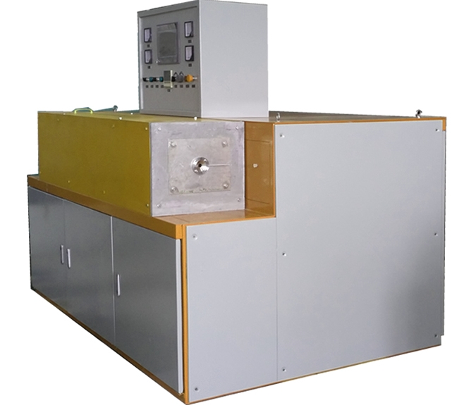
Intermediate frequency induction heating copper wire annealing equipment
Intermediate frequency induction heating copper wire annealing equipment
1 ، نظرة عامة:
Intermediate frequency induction heating copper wire (copper tube ) annealing equipment is suitable for on-line annealing of copper wire (brass alloy outer sheath). The penetration depth and hardness are according to the specific requirements of customers to achieve stress removal and softening of the brass alloy. The purpose of the outer sheath.
Equipment introduction The complete set of equipment is designed and manufactured according to the mechatronics structure. Among them, the intermediate frequency power supply is a set of 6- pulse thyristor KGPS200KW/8KHZ intermediate frequency power supply, the load is a set of GTR series induction heating furnace, and the equipment is equipped with a set of reactive power compensation capacitor bank. The device is designed with manual and automatic power adjustment knobs, among which automatic is the temperature closed-loop control mode. The external control console is controlled by PLC (Siemens) and touch screen. The touch screen can easily input heating parameters, such as copper wire specifications, heating speed, annealing temperature, etc. After the parameters are input, the closed loop control system of the intermediate frequency power supply temperature will automatically adjust the output power, thereby Meet production needs. When a certain link in the production fails, the intermediate frequency power supply can be insulated according to the set temperature to avoid overburning the copper wire. The equipment is placed according to user requirements, facing the equipment from left to right, the operating table is placed toward the main equipment, which is conducive to the operator to observe the production situation and facilitate the adjustment of parameters.
Safety protection The equipment has complete safety protection measures, such as water shortage protection, phase lack protection, over current protection, over voltage protection, under voltage protection, high water temperature protection, etc., and there is an audible and visual alarm device for faults. The equipment is configured according to 200KW , leaving enough power margin to ensure continuous and stable production of the equipment for 24 hours. All exposed conductors are installed in the electric control box with a lock, and there are eye-catching safety reminders, so no electrical safety accidents will occur. Each interlocking device can avoid damage to equipment or copper wires due to manual misoperation.
هيكل المعدات تغطي المجموعة الكاملة من المعدات مساحة حوالي 2000 * 1500 مم ، مع ارتفاع مركز يبلغ 1000 مم. تم دمج مصدر الطاقة مع جسم فرن التسخين ، ويتم استخدام مسامير التمدد لإصلاحه. تم تصميم الجهاز بوحدة تحكم خارجية ، والتي يمكن ترتيبها حسب الرغبة وفقًا لظروف الموقع ، وهي ملائمة للتشغيل. تركيب الجهاز بسيط وسريع. يحتاج المستخدمون فقط إلى توصيل أنابيب مدخل ومخرج المياه بمدخل المياه وأنابيب الخروج للمعدات (فوهة واحدة لكل مدخل ومخرج مياه) ، وتوصيل الأسلاك ذات الثلاث مراحل بالطرف العلوي للجهاز.
2 , induction heating annealing apparatus copper
المقياس التقني
2 – 1 معلمات تكنولوجيا المواد
مادة قطعة العمل: من خلال سلك أرضي (الداخل عبارة عن موصل نحاسي ذو قلب مجدول ، والجزء الخارجي مغطى بإحكام بغلاف خارجي من سبائك النحاس)
طريقة التلدين: التسخين التعريفي المستمر عبر الإنترنت
مواصفات المواد: φ 6- φ 13 مم ، سمك الجدار 1 مم
2 .2 المتطلبات الفنية الرئيسية للتدفئة
درجة الحرارة الأولية: 20 درجة مئوية ؛
درجة حرارة التلدين: يمكن التحكم فيها وتعديلها في نطاق 600 درجة مئوية ؛ دقة اختبار درجة الحرارة لطبقة سبائك النحاس هي ± 5 ، ودقة التحكم في درجة الحرارة للتسخين التعريفي هي ± 20 ℃.
عمق التسخين: 2 مم ؛
سرعة خط العملية: في غضون 30 م / دقيقة (السرعة القصوى للخط ليست أعلى من 30 م / دقيقة) ؛
ارتفاع المركز لخط الإنتاج: 1 متر ؛
2.3 اختيار التكنولوجيا للمعدات الكاملة
تشتمل المجموعة الكاملة من المعدات على نظام التحكم في إمداد الطاقة بالتردد المتوسط ، ونظام قياس درجة حرارة الألياف الضوئية بالأشعة تحت الحمراء البعيدة ، ونظام التحكم في درجة الحرارة المغلقة ، وبنك مكثف تعويض الطاقة التفاعلية ، وجسم فرن التلدين بالتسخين التعريفي ، إلخ.
نظام التحكم في طاقة التردد المتوسط:
2.3.1 مصدر طاقة التردد المتوسط هو جهاز تردد متغير الثايرستور ، جهد الدخل 380 فولت ، 50 هرتز ، وطاقة الخرج 200 كيلو وات. يمكن ضبط الطاقة يدويًا أو تلقائيًا وفقًا لدرجة الحرارة المحددة. تردد الخرج هو 8 كيلو هرتز (تتبع التردد التلقائي). يتم تحديد لون الخزانة وفقًا لمتطلبات المستخدم ، وحجم المخطط هو 2000 × 1500 × 1300 مم ، وارتفاع المركز 1000 مم.
2.3.2 نوع خرطوشة رف السيليكون مجتمعة
يعتمد الجزء المعدل والعاكس في الثايرستور أحدث إطار من السليكون المركب المعياري مع طلب براءة الاختراع. طريقة التثبيت هذه تجعل فك وتركيب الثايرستور أكثر ملاءمة وعلمية. عند استبدال الثايرستور ، فقط قم بفكه. يمكن أن يحل مسمار التثبيت محل أي عنصر من عناصر الثايرستور في المجموعة. علاوة على ذلك ، فإن طريقة التثبيت هذه تقلل تمامًا من حجم مكون SCR ، مما لا يزيد فقط من مساحة التشغيل في الخزانة الكهربائية ، ولكنه يقلل أيضًا بشكل كبير من فقد الخط.
2.3.3 مفاعل تنعيم DC ذو سعة كبيرة
مفاعل التنعيم مهم جدًا لتزويد الطاقة الصلبة ، وله وظيفتان. أولاً ، اجعل تيار الإخراج للمقوم سلسًا ومستقرًا. ثانيًا ، عندما يكون الثايرستور العاكس قصير الدائرة ، يكون معدل نمو تيار الدائرة القصيرة وحجم الحد الأقصى لتيار الدائرة القصيرة محدودًا. إذا كان تصميم المعلمة لمفاعل المرشح غير معقول ، أو أن المادة الأساسية ليست جيدة أو أن عملية التصنيع ليست جيدة بما فيه الكفاية ، فسيكون لها تأثير كبير على موثوقية العمل لمصدر طاقة التردد المتوسط.
2.3.4 SCR سعة كبيرة
من أجل ضمان موثوقية تشغيل المعدات ، يستخدم كل من الثايرستور المعدل والعاكس السيليكون KP و KK القائم على محطة Xiangfan لضمان التشغيل المستقر للمعدات.
2.3.5 استخدم خطوط التعويض المتسلسلة والمتوازية لتقليل فقد خطوط النقل
من أجل تقليل الخسارة على خط نقل التردد المتوسط ، يتم توصيل مكثف التعويض للعاكس في سلسلة وشكل مضاعفة الجهد المتوازي
2.3.6 معلمات الدائرة الرئيسية وأساس اختيار المكونات
تظهر المعلمات المقدرة للدائرة الرئيسية لمصدر طاقة التردد المتوسط في الجدول التالي:
| مشروع المدى | KGPS200 / 8 |
| جهد الإدخال (V) | 38 |
| تيار مستمر (A) | 400 |
| جهد التيار المستمر (V) | 500 |
| جهد عمل ملف التعريفي (V) | 750 |
| تردد العمل (H z) | 800 |
The inductor is composed of a furnace shell, an induction coil, a stainless steel water collector and a furnace lining. The induction coil is combined with the parameters of the annealed copper alloy tube to optimize the design with special computer software and make it in combination with actual experience. It can ensure the best electromagnetic coupling efficiency under the same capacity. Induction coils with 99.99% of T2 rectangular copper wire made, the induction coil outer insulating electrostatic spray process the epoxy resin insulating layer of high strength, pressure-resistant insulating layer is greater than 5000V .
The inner layer of the induction coil is made of white corundum lining, and the outside of the lining and between the coils are fixed with refractory cement (American Union Mine), which can play a role in insulation and heat preservation. At the same time, the strength of the white corundum lining is further increased, effectively avoiding copper wire damage to the lining.
يتم تجميع كل المياه الداخلة والخارجة من المستشعر في اثنين من مصائد المياه المصنوعة من الفولاذ المقاوم للصدأ ، والتي يتم توصيلها بأنابيب مدخل ومخرج المياه الرئيسية. مجمع المياه الفولاذي المقاوم للصدأ جميل وعملي ، والذي يمكن أن يتجنب بشكل فعال تأثير تبديد الحرارة لملف الحث بسبب تآكل أنبوب الماء وانسداد المجرى المائي.