- 18
- Apr
Intermediate frequency induction heating copper wire annealing equipment
Intermediate frequency induction heating copper wire annealing equipment

1 , ภาพรวม:
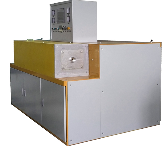
Intermediate frequency induction heating copper wire (copper tube ) annealing equipment is suitable for on-line annealing of copper wire (brass alloy outer sheath). The penetration depth and hardness are according to the specific requirements of customers to achieve stress removal and softening of the brass alloy. The purpose of the outer sheath.
Equipment introduction The complete set of equipment is designed and manufactured according to the mechatronics structure. Among them, the intermediate frequency power supply is a set of 6- pulse thyristor KGPS200KW/8KHZ intermediate frequency power supply, the load is a set of GTR series induction heating furnace, and the equipment is equipped with a set of reactive power compensation capacitor bank. The device is designed with manual and automatic power adjustment knobs, among which automatic is the temperature closed-loop control mode. The external control console is controlled by PLC (Siemens) and touch screen. The touch screen can easily input heating parameters, such as copper wire specifications, heating speed, annealing temperature, etc. After the parameters are input, the closed loop control system of the intermediate frequency power supply temperature will automatically adjust the output power, thereby Meet production needs. When a certain link in the production fails, the intermediate frequency power supply can be insulated according to the set temperature to avoid overburning the copper wire. The equipment is placed according to user requirements, facing the equipment from left to right, the operating table is placed toward the main equipment, which is conducive to the operator to observe the production situation and facilitate the adjustment of parameters.
Safety protection The equipment has complete safety protection measures, such as water shortage protection, phase lack protection, over current protection, over voltage protection, under voltage protection, high water temperature protection, etc., and there is an audible and visual alarm device for faults. The equipment is configured according to 200KW , leaving enough power margin to ensure continuous and stable production of the equipment for 24 hours. All exposed conductors are installed in the electric control box with a lock, and there are eye-catching safety reminders, so no electrical safety accidents will occur. Each interlocking device can avoid damage to equipment or copper wires due to manual misoperation.
โครงสร้างอุปกรณ์ ชุดอุปกรณ์ครบชุดครอบคลุมพื้นที่ประมาณ 2000*1500 มม. โดยมีความสูงตรงกลาง 1000 มม. ตัวจ่ายไฟถูกรวมเข้ากับตัวเตาให้ความร้อน และใช้สลักเกลียวขยายเพื่อแก้ไข อุปกรณ์ได้รับการออกแบบด้วยคอนโซลภายนอกซึ่งสามารถจัดเรียงได้ตามต้องการตามสภาพของไซต์ซึ่งสะดวกต่อการใช้งาน การติดตั้งอุปกรณ์ทำได้ง่ายและรวดเร็ว ผู้ใช้จำเป็นต้องเชื่อมต่อท่อน้ำเข้าและทางออกกับท่อน้ำเข้าและทางออกของอุปกรณ์ (หนึ่งหัวฉีดสำหรับทางเข้าและทางออกของน้ำแต่ละท่อ) และเชื่อมต่อสายสี่เฟสสามเฟสกับปลายด้านบนของอุปกรณ์
2 , induction heating annealing apparatus copper
พารามิเตอร์ทางเทคนิค
2 .1 พารามิเตอร์เทคโนโลยีวัสดุ
วัสดุชิ้นงาน : ผ่านสายกราวด์ (ด้านในเป็นตัวนำแกนทองแดงตีเกลียว ด้านนอกหุ้มด้วยปลอกหุ้มด้านนอกเป็นโลหะผสมทองเหลืองอย่างแน่นหนา)
วิธีการหลอม: เครื่องทำความร้อนเหนี่ยวนำแบบต่อเนื่องออนไลน์
ข้อมูลจำเพาะของวัสดุ: φ 6- φ 13 มม. ความหนาของผนัง 1 มม
2 .2 ข้อกำหนดทางเทคนิคหลักของการให้ความร้อน
อุณหภูมิเริ่มต้น: 20 ℃;
อุณหภูมิการหลอม: ควบคุมและปรับได้ภายในช่วง 600 ℃; ความแม่นยำในการทดสอบอุณหภูมิของชั้นโลหะผสมทองเหลืองคือ ± 5 ℃ และความแม่นยำในการควบคุมอุณหภูมิของการทำความร้อนแบบเหนี่ยวนำคือ ± 20 ℃
ความลึกของเครื่องทำความร้อน: 2mm ;
ความเร็วสายกระบวนการ: ภายใน 30 เมตร/นาที (ความเร็วสายสูงสุดไม่เกิน 30 เมตร/นาที );
ความสูงของศูนย์สายการผลิต: 1m ;
2.3 เทคโนโลยีการเลือกอุปกรณ์ที่ครบครัน
อุปกรณ์ครบชุดประกอบด้วยระบบควบคุมการจ่ายไฟความถี่กลาง ระบบวัดอุณหภูมิใยแก้วนำแสงฟาร์อินฟราเรด ระบบควบคุมวงปิดอุณหภูมิ ธนาคารตัวเก็บประจุชดเชยกำลังรีแอกทีฟ ตัวเตาหลอมความร้อนเหนี่ยวนำ ฯลฯ
ระบบควบคุมพลังงานความถี่กลาง:
2.3.1 แหล่งจ่ายไฟความถี่กลางเป็นอุปกรณ์ความถี่ตัวแปรไทริสเตอร์ แรงดันไฟฟ้าขาเข้าคือ 380V, 50Hz และกำลังขับ 200KW สามารถปรับกำลังไฟได้ด้วยตนเองหรือโดยอัตโนมัติตามอุณหภูมิที่ตั้งไว้ ความถี่เอาต์พุตคือ 8KHz (การติดตามความถี่อัตโนมัติ) สีของตู้ถูกกำหนดตามความต้องการของผู้ใช้ ขนาดเค้าร่างคือ 2000 × 1500 × 1300 มม. และความสูงตรงกลางคือ 1000 มม.
2.3.2 ประเภทตลับรวมชั้นวางซิลิกอนรวม
ส่วนวงจรเรียงกระแสและอินเวอร์เตอร์ของไทริสเตอร์ใช้เฟรมซิลิกอนแบบรวมโมดูลาร์ล่าสุดที่มีการยื่นขอจดสิทธิบัตร วิธีการติดตั้งนี้ทำให้การถอดประกอบและการประกอบไทริสเตอร์สะดวกและเป็นวิทยาศาสตร์มากขึ้น เมื่อเปลี่ยนไทริสเตอร์ ให้คลายออก โบลต์ที่ขันแน่นสามารถแทนที่องค์ประกอบไทริสเตอร์ใดๆ ในชุดประกอบได้ นอกจากนี้ วิธีการติดตั้งนี้ยังช่วยลดปริมาณของส่วนประกอบ SCR ได้อย่างเต็มที่ ซึ่งไม่เพียงเพิ่มพื้นที่การทำงานในตู้ไฟฟ้าเท่านั้น แต่ยังช่วยลดการสูญเสียสายได้อย่างมาก
2.3.3 เครื่องปฏิกรณ์ปรับให้เรียบ DC ความจุสูง
เครื่องปฏิกรณ์ปรับให้เรียบเป็นสิ่งสำคัญมากสำหรับการจ่ายไฟแบบแข็ง โดยมีหน้าที่สองประการ ขั้นแรก ทำให้กระแสไฟขาออกของวงจรเรียงกระแสเรียบและเสถียร ประการที่สอง เมื่อไทริสเตอร์อินเวอร์เตอร์ลัดวงจร อัตราการเติบโตของกระแสไฟลัดวงจรและขนาดของกระแสไฟลัดวงจรสูงสุดจะถูกจำกัด หากการออกแบบพารามิเตอร์ของเครื่องปฏิกรณ์กรองไม่สมเหตุสมผล วัสดุหลักไม่ดีหรือกระบวนการผลิตไม่ดีพอ ก็จะส่งผลกระทบอย่างมากต่อความน่าเชื่อถือในการทำงานของแหล่งจ่ายไฟความถี่กลาง
2.3.4 SCR . ความจุสูง
เพื่อให้แน่ใจว่าการทำงานของอุปกรณ์มีความน่าเชื่อถือ ทั้งเครื่องแปลงกระแสไฟฟ้าและอินเวอร์เตอร์ไทริสเตอร์ใช้ซิลิโคน KP และ KK ความจุสูงของสถานี Xiangfan เพื่อให้แน่ใจว่าอุปกรณ์ทำงานได้อย่างเสถียร
2.3.5 ใช้เส้นชดเชยแบบอนุกรมและขนานเพื่อลดการสูญเสียสายส่ง
เพื่อลดการสูญเสียบนสายส่งความถี่กลาง ตัวเก็บประจุชดเชยของอินเวอร์เตอร์จะเชื่อมต่อแบบอนุกรมและแบบแรงดันคู่ขนาน
2.3.6 พารามิเตอร์วงจรหลักและเกณฑ์การเลือกส่วนประกอบ
พารามิเตอร์พิกัดของวงจรหลักของแหล่งจ่ายไฟความถี่กลางแสดงในตารางต่อไปนี้ :
| โครงการระยะยาว | KGPS200/8 |
| แรงดันไฟฟ้าขาเข้า ( วี ) | 38 |
| กระแสตรง (A) | 400 |
| แรงดันไฟฟ้ากระแสตรง (V) | 500 |
| แรงดันใช้งานของขดลวดเหนี่ยวนำ (V) | 750 |
| ความถี่ในการทำงาน ( H z ) | 800 |
The inductor is composed of a furnace shell, an induction coil, a stainless steel water collector and a furnace lining. The induction coil is combined with the parameters of the annealed copper alloy tube to optimize the design with special computer software and make it in combination with actual experience. It can ensure the best electromagnetic coupling efficiency under the same capacity. Induction coils with 99.99% of T2 rectangular copper wire made, the induction coil outer insulating electrostatic spray process the epoxy resin insulating layer of high strength, pressure-resistant insulating layer is greater than 5000V .
The inner layer of the induction coil is made of white corundum lining, and the outside of the lining and between the coils are fixed with refractory cement (American Union Mine), which can play a role in insulation and heat preservation. At the same time, the strength of the white corundum lining is further increased, effectively avoiding copper wire damage to the lining.
น้ำเข้าและออกจากเซ็นเซอร์ทั้งหมดจะถูกรวบรวมไว้ในกับดักน้ำสแตนเลสสองอัน ซึ่งเชื่อมต่อกับท่อน้ำเข้าและทางออกหลัก ตัวเก็บน้ำสแตนเลสมีความสวยงามและใช้งานได้จริง ซึ่งสามารถหลีกเลี่ยงอิทธิพลของการกระจายความร้อนของขดลวดเหนี่ยวนำอันเนื่องมาจากการกัดกร่อนของท่อน้ำและการอุดตันของทางน้ำได้อย่างมีประสิทธิภาพ
