- 08
- Aug
How does the double-frequency gear induction heating furnace quenching production line work?
How does the double-frequency gear induction heating furnace quenching production line work?
The American TOCC0 company once designed and manufactured a double-frequency induction furnace quenching and quenching production line for internal gears and sun gears for a transmission factory. This production line consists of two 100kW, 10kHz intermediate frequency solid-state power supplies, one for the internal gear and the other for the sun gear; the high-frequency power supply is 200kW, 450kHz.
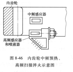
Quenching and tempering of internal gears The internal gears of this production line are unloaded one piece at a time and are operated by two opposed cylinders. When the workpiece is in the No. 1 loading position, a proximity switch acts to make the pneumatic reciprocating rod push the workpiece to the quenching station. This station has a variable-speed servo and vertical scanning bracket, the gear reaches the quenching station, and the other The proximity switch acts, so the vertical scanner lifts the internal gear from the reciprocating rod and places the workpiece in the orientation position below the sensor. There are two proximity switches used as a dedicated positioning indicator. If the wrong position is set, the workpiece That is, return to the reciprocating rod for refilling. Misplacement Is, the machine tool stops running, and at the same time, a diagnostic display screen indicates that the workpiece is not in the quenching station. If the internal gear is positioned correctly and accepted by the workpiece orientation station, the scanning mechanism will send it to the sensor. Once the sensor is located in the internal gear, the intermediate frequency power supply starts heating, the workpiece rotates, and the scanning mechanism lowers the workpiece, so that the sensor scans and preheats the full length of the internal gear. The schematic diagram of internal gear intermediate frequency preheating and high frequency scanning quenching is shown in Figure 8-46.
After the intermediate frequency preheating is completed, the scanning positioner rises and returns to the original position, the power switch is switched to the high frequency power supply, the workpiece rotates down again, and the preheated gear is scanned and quenched with high frequency. After the quenched internal gear descends to the reciprocating rod, the reciprocating rod pushes the workpiece to the tempering station, and its positioning signal action is the same as that of the quenching station. Tempering is a one-time heating method, the workpiece is rotating during tempering, and the tempering power is small, and it is carried out during the period of high-frequency hardening of the gear.
After the tempering process is completed, the gear is lowered to the reciprocating rod and pushed to the cooling station, cooled by the spray head to the loading and unloading temperature, and then the workpiece is pushed to the sub-inspection station (qualified or rejected). Rejection is determined by many detection devices. If the internal gear is determined to be rejected, a pneumatic discharge rod installed on the side will push the gear horizontally and slide to the rejection discharge box. If the gear is qualified, then Push to the discharge box.
(2) The quenching and tempering of the sun gear The double-frequency quenching diagram of the sun gear is shown in Figure 8-47.
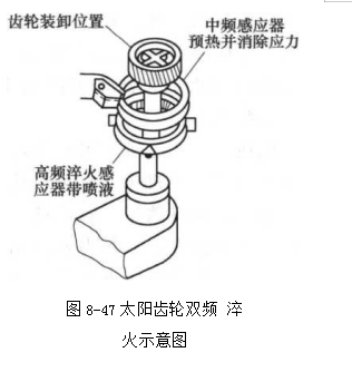
During intermediate frequency preheating and high frequency heating, the workpiece is rotating. After high frequency heating, the quenching liquid is sprayed from the combined inductor. Due to the structural characteristics of the sun gear, the quenching liquid must be removed before it enters the tempering station. There is a work-piece light shaking station that lifts the sun gear to 110. Angle and shake to remove the attached quenching liquid. The tempering process uses intermediate frequency, which happens to be the time period for high-frequency heating of this gear. During tempering, the workpiece is also rotating, and the tempered gear enters the cooling station. After spray cooling, it shakes slightly again. After dewatering, it enters the inspection station for qualified and reject sorting.
(3) Detecting instrument and its control The scanning speed, heating cycle and quenching cooling are controlled by the programmer (Modicon 984), as well as the input and output cards, and the programmer (480
Gould), servo controller (410 Gould), D. C. motor controller are used to control the rotation speed of the workpiece. The servo controller is used to control the scanning speed, the fault diagnosis screen displays the fault, and the energy monitor provides real energy. The quenching and tempering sensors have grounding protection. If the workpiece collides with the sensor, the fault will be displayed on the screen and the machine tool will stop working.
(4) The water cooling system is composed of a stainless steel water pump, a plate heat exchanger, a float switch, a water temperature monitor, and an automatic thermostat valve.