
- 07
- Sep
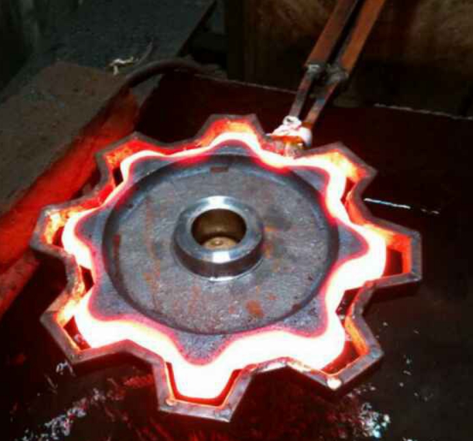
Gear ring high frequency quenching equipment
Gear ring high frequency quenching equipment
Gear ring high-frequency quenching equipment is a kind of equipment for hardening the gear ring. When quenching is carried out by induction hardening along the tooth groove, the common frequency is 1 ~ 30kHz, and the gap between the inductor and the part is controlled at 0.5 ~ 1mm. It is necessary to precisely control the sensor to be very symmetrical with the adjacent two tooth sides, and strictly control the gap between the tooth side and the tooth root.
Common methods of induction hardening of gear ring
There are four types of gear ring induction heating hardening, along the tooth groove induction hardening, tooth-by-tooth induction hardening, rotary induction hardening, and dual-frequency induction hardening. The induction hardening along the tooth groove and the tooth-by-tooth induction hardening process are particularly suitable for external and internal gears with large diameters (up to 2.5m or more) and large modulus, but not suitable for small diameter and small modulus gears (modulus). Less than 6).
1. Induction hardening along the tooth groove: harden the tooth surface and the tooth root, and there is no hardened layer in the middle of the tooth top. This method heat treatment deformation is small, but the production efficiency is low.
2. Tooth-by-tooth induction hardening: the tooth surface is hardened, and the tooth root has no hardened layer, which improves the wear resistance of the tooth surface, but due to the existence of the heat-affected zone, the strength of the tooth will be reduced, as shown in Figure 2.
3. Rotary induction hardening: single-turn scanning hardening or multi-turn heating and hardening at the same time, the teeth are basically hardened, and the hardened layer of the tooth root is shallow. Suitable for small and medium gears, but not suitable for high-speed and heavy-duty gears.
4. Double-frequency induction hardening: preheating the tooth slot at intermediate frequency and heating the tooth top with high frequency to obtain a hardened layer that is basically distributed along the tooth profile.
Common problems and countermeasures in the high-frequency hardening process of the gear ring (here mainly take the induction hardening method along the tooth groove as an example)
1. The hardened layer is unevenly distributed, one side has high hardness and deep hard layer, and the other side has low hardness and shallow hard layer. This is because the induction hardening along the tooth groove has high position sensitivity compared with the rotary induction hardening of the ring inductor. It is necessary to design and manufacture a high-precision positioning device to ensure a highly symmetrical distribution of the gap between the tooth side and the inductor. If it is not symmetrical, it may also cause a short circuit between the sensor and the part and arc on the side with a small gap, which may damage the sensor early.
2. Annealing of hardened tooth side. The reason is that the auxiliary cooling device is not adjusted in place or the amount of coolant is insufficient.
3. The copper tube at the tip of the sensor is overheated. When using the non-embedded scan quenching process along the tooth groove, because the gap between the inductor and the part is relatively small, the heat radiation from the heating surface and the limited size of the nose copper tube make the copper tube easy to overheat and burn out. , So that the sensor is damaged. Therefore, the sensor must ensure that there is sufficient flow and pressure of the cooling medium to pass.
4. The shape and position of the ring gear change during the sensing process. When scanning and quenching along the tooth groove, the processed tooth will bulge out 0.1~0.3mm. Deformation, thermal expansion, and improper sensor adjustment can cause parts to collide with the sensor and damage it. Therefore, the thermal expansion factor should be considered when determining the gap between the inductor and the tooth side, and an appropriate limit device should be used to ensure the gap.
5. The performance of the inductor’s magnetism is degraded. The working conditions of the magnetic conductor are bad, and under the environment of high-density magnetic field and high current, it is very easy to be damaged by overheating. At the same time, quenching medium and corrosion will make its performance degraded. Therefore, it is necessary to do a good job in the daily maintenance and maintenance of the sensor.