- 13
- Sep
Transition from chemical steel to steelmaking by adopting air-permeable brick intermediate
Transition from chemical steel to steelmaking by adopting air-permeable brick intermediate frequency furnace scouring technology
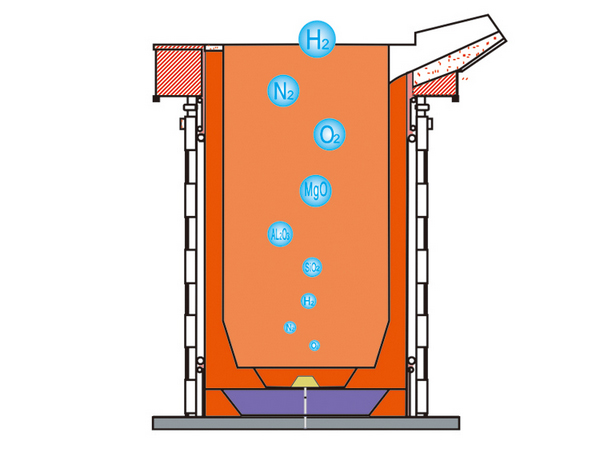
Intermediate frequency furnace refining technology has transformed ordinary induction melting furnaces from chemical steel to steelmaking. In many cases, the quality of molten steel (alloy) has reached the refining quality level of AOD furnace, LF refining furnace, and VD vacuum degassing furnace.
Advantages of using gas diffuser:
1. Promote the floating of inclusions in the molten steel, reduce the inclusions, and improve the quality of the molten metal;
2. Improve the use of additives;
3. Reduce the scrap rate;
4. Extend the life of furnace lining;
5. Low investment;
6. Give the induction furnace the refining function to provide strong technical support for improving the quality of molten metal and developing new products.
, How to install the gas diffuser
1.1 Preparation before installation
1) Machining a ¢18mm round hole in the center of the bottom of the induction furnace shell (part of the furnace shape has been reserved) to facilitate the installation of the gas diffuser pipeline.
2) Brush H-edge paint on the induction coil and apply coil paste. Some furnaces are still laying mica plates and asbestos cloth on the inner wall of the coil paste.
3) Prepare an iron tube with a wall thickness of 1~2mm, a diameter of 200~350mm according to the size of the furnace, and a height of 250~300mm. The outer surface is flat and clean. For easy extraction, two handles can be welded.
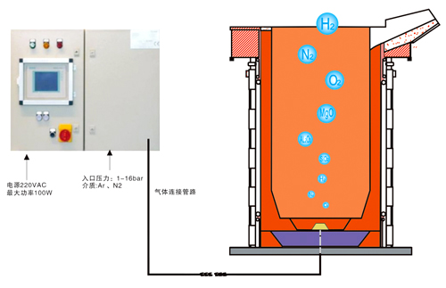
4) Prepare the gas source, such as bottled argon, nitrogen, etc. The gas purity is required to be 99.99%. When the gas volume is large, several gas cylinders can be formed into a busbar; a pressure gauge is connected to the outlet of the gas source (range 0~ 2Mpa), flow meter (range 0~250L/min), needle valve (compared to control the air flow); in industrial mass production, you can install the “intelligent gas control system” (provided by the company), so that the gas can be high, intelligent, Reliable control (see company product catalog or website for details).
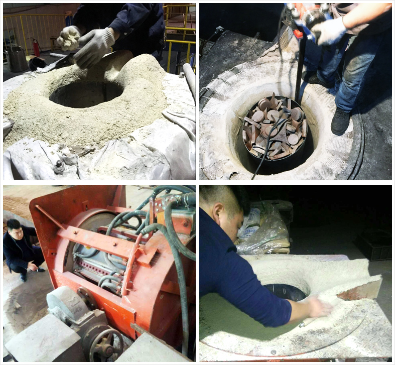
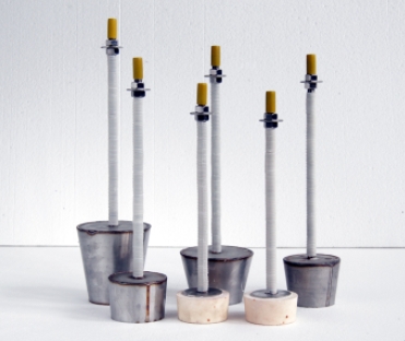
1.2 Install the gas diffuser
After the above preparations are completed, pass the gas diffuser back tube (the back tube of the diffuser is an external thread, M16×2mm) through the round hole at the bottom, fix it on the bottom of the furnace with a nut and a gasket, and make the upper surface of the gas diffuser The height is about 100mm lower than the upper surface of the bottom material of the induction furnace (as shown in the figure), and the height of the upper surface of the gas diffuser is lower than or equal to the height of the bottom ring of the induction coil. Connect the adapter (pagoda head) to the rear tube of the diffuser, and then connect it to the gas cylinder hose; you can also directly connect the metal hose to the rear tube of the gas diffuser to ensure that the gas pipeline interface does not leak (as shown in the figure). Don’t pay attention: during the connection process, no debris, dust, etc. should fall into the pipeline.
Afterwards, cover the gas diffuser with a pre-prepared iron tube, calibrate the position of the iron tube, place the diffuser in the center of the iron tube, pour the dry vibrating material into the outside of the iron tube, and then follow the induction furnace dry vibrating material construction process The outside of the iron tube drum is hit with a dry vibrating material to make it compact and in line with the elevation of the furnace bottom material. After the vibrating and ramming of the dry vibrating material on the outside of the iron tube, slowly pull out the iron tube, tear off the adhesive paper on the gas diffuser, and pour the “breathable material” into the central pit of the furnace bottom. 100mm, ramming and compacting the breathable material layer by layer, and make the height of the breathable material and the furnace bottom dry vibrating material the same. Be careful not to damage the gas diffuser when using the fork vibrator. After the inner venting material is laid, use the furnace fork to mark the deep fork along the circumference for 2 to 3 weeks, and insert the tips of the furnace fork into the inner and outer sides of the circumference at the same time. Use a vibrator equipped with a flat head to repeatedly vibrate and ram the fork marks on the circumference and the upper part of the breathable material to flatten and compact the gas diffuser. The installation of the gas diffuser is completed.
After that, complete the subsequent furnace-making process: align the steel mold core (steel mold core should be made of a steel plate with a thickness of 6mm or more, which is conducive to the sintering of the furnace lining) → follow the induction furnace dry vibrating material construction process to drill the furnace wall and furnace wall The height of the dry material reaches about 50mm from the furnace mouth→the upper part of the wet material blasting furnace wall→the wet material blasting furnace mouth and mouth. If the steel mold core is not drawn, it must be melted into the molten steel with the furnace lining sintered.
2. Furnace lining sintering and trial blowing
The lining sintering also includes the sintering of “breathable material”, which is very important. The quality of sintering is related to the life of the lining and the use of the gas diffuser.
The furnace for melting steel should use dense scrap. For example, use short and high-quality scrap as much as possible. The temperature rises at a rate of 200-300°C per hour to 1100°C for about 1 hour, and then the temperature rises at a rate of 300°C/hour. The height should rise slightly above the dry material/wet material connection, and keep it at 1680~1700℃ for 1~2 hours.
After sintering and holding, you can try blowing.
Gradually open the needle valve and manually observe and adjust the gas flow to ensure that there are bubbles and spots on the molten steel surface to avoid excessive gas volume, molten steel tumbling, and exposure to the air causing secondary oxidation and slag entrapment.