- 02
- Jan
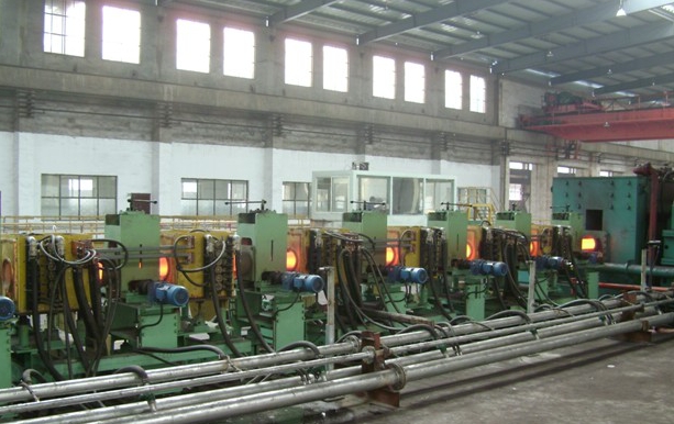
Working principle of sucker rod heat treatment line
Working principle of sucker rod heat treatment line
1. Feeding rack on sucker rod heat treatment line (including bulk bundling device and disc feeder): the feeding rack is for stacking steel pipes to be heated, and the rack is made of 16mm thick steel plate and 20#, hot-rolled I-shaped It is made of welded steel, the width of the table is 200mm, the table has a slope of 3°, and 20 φ159 steel pipes can be placed. The platform and the column are welded, and the whole bundle of materials is hoisted on the platform by a crane during work, and the bundle is manually unbundled. The bulk bale device is driven by an air cylinder. As long as the command is turned on, the bulk bale support will be opened, and the steel pipe will roll to the disc feeder to hold it. The disc feeder is equipped with a total of 7 disc reclaimers on the same axis. As soon as the instruction is given, the steel pipe needs to be heated, and it will automatically roll to the end of the table according to the beat (ie time). Stopped in the middle position.
2. Feeding and flipping mechanism of sucker rod heat treatment line: The feeding and flipping mechanism is the same as the lever type flipping machine. The purpose is to transfer the workpiece from this station to another, but the structure is fundamentally different. The working principle is There is a big difference, the flip mechanism is to hold the material smoothly, and then put the material down steadily, with good centering and no impact or impact. There are 9 flippers, all of which are arranged, and the working surface is inclined 3° from high to low. Driven by φ250 by 370 stroke cylinder, when the working pressure is 0.4Mpa, the pulling force is 1800kg, which is 3 times of the heaviest steel pipe. The flip and flip are connected by connecting rods and tie rods with hinges, and 9 flips are working. Simultaneous rise and fall, good synchronization.
3. V-shaped roller conveyor system for sucker rod heat treatment line:
3.1. The roller conveying system is composed of 121 sets of independently driven V-shaped rollers. There are 47 V-shaped rollers on the quenching and normalizing line, 9 sets of fast-feeding V-shaped rollers (including inverter), 24 sets of heating spray V-shaped rollers (including inverter), and 12 sets of quick-lift rollers (including inverter) ). The power is driven by a cycloid pinwheel reducer, the model is XWD2-0.55-57, the speed of the quick-lift roller is 85.3 rpm, the forward speed is 50889 mm/min, and the steel pipe is transmitted in 19.5 seconds to reach the end point. There are 37 sets of tempering line, 25 sets of heating V-shaped rollers (including frequency converter), 12 sets of quick-lift rollers (including frequency converter), and the power adopts cycloidal pinwheel reducer, model XWD2-0.55-59, quick-lift The rotation speed of the roller is 85.3 rpm, the forward speed is 50889 mm/min, and the steel pipe reaches the end point in 19.5 seconds. There are V-shaped rollers between the two cooling beds, all of which are fast rollers. The V-shaped rollers are installed on three production lines and arranged at 15° on the same center. The distance between the V-shaped roller and the V-shaped roller is 1500mm, and the diameter of the V-shaped roller is φ190mm. Except for the V-shaped roller at the feed end (the feed end is cold material), all other V-shaped roller rotating shafts are equipped with cooling water devices. The supporting roller adopts an outer spherical bearing with a vertical seat. Variable frequency motor speed control, equipped with frequency converter, the speed adjustment range is 38.5 revolutions/min~7.5 revolutions/min. The conveying forward speed is 22969mm/min~4476mm/min, and the steel pipe rotation range is: 25.6 revolutions/min~2.2 revolutions/min.
3.2. The sucker rod heat treatment line is calculated according to the annual output requirements. If the output per hour is 12.06 tons, the steel pipe advance speed is 21900mm/min~4380mm/min.
3.3. The result: the design advancement speed of the scheme meets the production requirements.
3.4. The speed of the frequency conversion motor is controlled by the frequency converter, and the time is about 3 seconds to connect the steel pipe end to end. 2.3.5 The steel pipe after normalizing and quenching enters another station smoothly. When the end of the steel pipe leaves the last spray ring, the head of the steel pipe enters the quick-lift raceway. The frequency converter controls the steel pipes that are connected end to end for about one second to separate automatically and reach the end to enter the next station.
3.6. The steel pipe after normalizing and tempering can enter the cooling bed in time. When the end of the steel pipe leaves the exit of the last section of the sensor, the head of the steel pipe enters the quick-lift raceway, and the frequency converter controls the end and the end of the steel pipe for about one second. It separates quickly, reaches the end, and enters the cooling bed through the flip mechanism.
3.7. Floating pressure roller: The floating pressure roller and the transfer V-shaped roller are combined together, and the front end of each group of sensors is installed as a set. 4 sets of normalizing and quenching, 3 sets of tempering, 7 sets in total. Due to the fast transmission speed, it is set to prevent the steel pipe from damaging the sensor due to the radial bounce. The floating pressure roller can be adjusted, and the range is suitable for steel pipes of various specifications. The gap between the steel pipe and the upper wheel is 4-6mm, which can be adjusted manually.
3.8 Tempering sensor moving device: When the steel pipe is normalized, in order to make the steel pipe smoothly enter the cooling bed, the tempering sensor must be withdrawn from the production line. Three sets of φ100×1000 cylinders pass the connected tempering sensors through the track and withdraw from the production line. The stroke does not need to be adjusted, push it forward, and the center of the track is the center of the sensor.